MSD 2922 Fuel Pump Return Kit Installation User Manual
Page 3
INSTALLATION INSTRUCTIONS
3
M S D
• W W W . A T O M I C E F I . C O M • ( 9 1 5 ) 8 5 7 - 5 2 0 0 • F A X ( 9 1 5 ) 8 5 7 - 3 3 4 4
REGULATOR CONNECTIONS AND ADJUSTMENT
The regulator inlet port is located on the bottom surface, and clearly marked with an identifier machined
in the housing (see Figure 4 below). Two (2) outlet ports are available, but typically only one (1) will
be used. Install the supplied -6AN port plug in the unused outlet port using a 5/16-inch hex key (Allen
wrench). The -6AN straight port fittings should be snugged with an 11/16-inch wrench or deep socket.
Install the supplied 1/8-27 NPT brass hose barb fitting in the upper regulator housing (see Figure 4
below) using a 7/16-inch wrench or deep socket. Thread sealer is not required on this fitting, but
can be used if desired. Connect an intake manifold vacuum / boost source to this fitting, or leave
it open to the atmosphere if manifold pressure compensation is not required. DO NOT plug this
opening. Ensure that contaminants (such as water and road spray) cannot enter the open fitting.
In the event that vacuum / boost reference is not required, a more cosmetically pleasing option is to
install a sintered metal exhaust muffler in this port (such as McMaster-Carr PN 4450K1-Bronze or PN
4402K51-Stainless Steel)
The 1/8-27 NPT port in the lower housing allows the installation of a fuel pressure gauge (direct or
remote-reading). If use of this port is not required, install the supplied stainless steel pipe plug using
a 3/16-inch hex key (Allen wrench). Use of a fuel compatible paste-type thread sealer is REQUIRED
on this plug. Thread sealing tape is also an option, but not recommended due to the potential for
particulate and debris generation.
Use a 5/32-inch hex key (Allen wrench) to adjust the regulator set point. Clockwise rotation (screw
advancing inward) increases the set point, and counter-clockwise rotation (screw advancing outward)
decreases the set point. When the desired set point has been reached, snug the jam nut using a
½-inch wrench.
Refer to the user installation instructions, supplied with the Atomic EFI kit, for regulator set point
recommendations.
Note: An overly lengthy and restrictive return line routing scheme may result in a non-negligible
pressure rise across the regulator-to-tank portion of the system. For this reason, the final
regulator adjustment should be made while monitoring the system fuel pressure (on the Atomic
hand-held Dash) with the engine at idle.
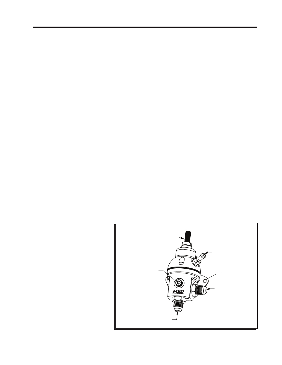
Figure 4 - Regulator Feature Identification Guide
MOUNTING
BRACKET
VACUUM / BOOST
REFERENCE PORT
(1/8-27 NPT)
OUTLET PORT
(1 OF 2)
ADJUSTMENT SCREW
AND LOCK NUT
INLET PORT
GAUGE PORT
(1/8-27 NPT)