Figure 3-1. default display, 1 field / current display, Figure 3-1 default display – American Magnetics 4Q06250PS-430 Integrated Power Supply System User Manual
Page 41: Field). refer to sections 3.2.1 an, Operation
Rev. 5
23
Operation
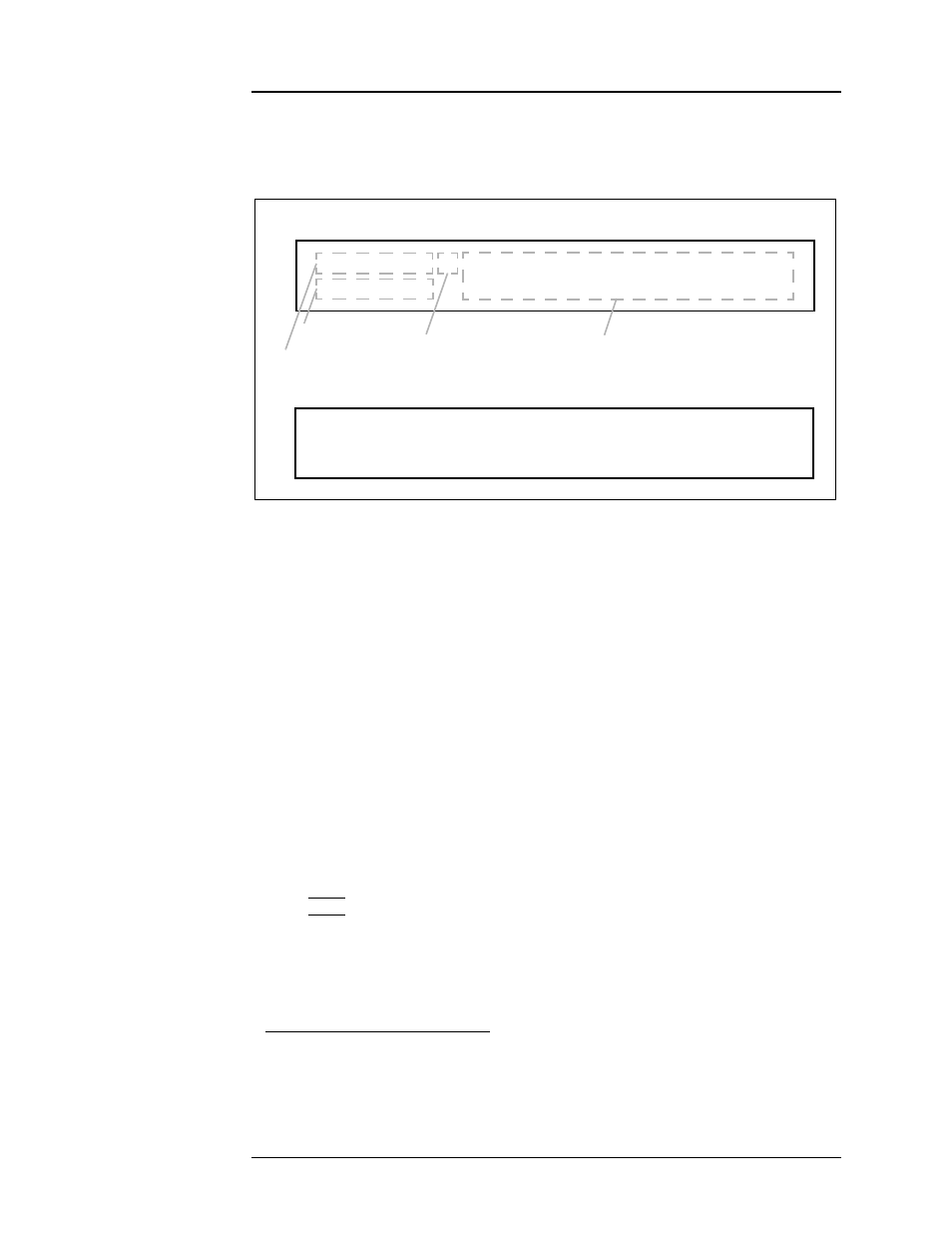
Default Display : Field / Current
display areas — the Field / Current Display area, the Voltage Display
area, the Status Indicator area and the Main Display area.
3.2.1
Field / Current Display
The field / current display indicates either the field strength or current
1
.
This is always displayed in the upper left corner of the display (see Figure
3-1), regardless of what else is being displayed on the Model 430
Programmer display. The parameter displayed (field or current) is toggled
by pressing
SHIFT
followed by
FIELD <> CURRENT
. Thus, if field strength
is being displayed, pressing
SHIFT
followed by
FIELD <> CURRENT
will
cause the current to be displayed; conversely, if current is being displayed,
pressing
SHIFT
followed by
FIELD <> CURRENT
will cause the field
strength to be displayed. Operating current is always displayed in
amperes (A). Operating field strength may be displayed in kilogauss (kG)
or tesla (T) if a coil constant has been specified in the setup
2
. If field
strength is being displayed, the units (kG or T) in which it is displayed can
be toggled by pressing
SHIFT
followed by
FIELD UNITS
.
Note
Note that the displayed field strength is not directly measured, but
rather is calculated by multiplying the coil constant entered in the
setup menu by the measured current flow of the Model 430 power
supply system.
1. The value is always displayed in current (A) when an installed persistent switch is in
the
cooled state
since the value represents power supply current only, independent
of magnet current/field.
2. Refer to section 3.10.2.2 on page 50.
+50.00 A — Status: Holding
+0.50 Vs
PSwitch Heater: ON
+50.00 A —
-10
0Vm
+10
+1.50 V s
|
''''|''''|''''|'''''|
Field / Current Display.
Default display showing ramp mode and persistent switch heater status:
Default display showing voltmeter:
Figure 3-1.
Default Display.
Voltage Display.
Status Indicator.
Main Display.