Series 235l, 9x8xxx-xx-xx-xx, 2,54 mm male headers – A P Products Male and Female Header User Manual
Page 16: Ordering information, A p products gmbh
A P Products GmbH
A P Products Ltd.
A P Products S.r.l.
Bäumlesweg 21 – 23
80 Cromwell Road
Viale Abruzzi, 87
71093 Weil im Schönbuch
Saffron Walden, CB11 4BE
20131 Milano
Germany
Great Britain
Italia
Tel: +49-7157-5348-0
Tel: +44-1799-526602
Tel: +39-02-29404697
Fax: +49-7157-5348-39
Fax: +44-1799-521408
Fax: +39-02-29523280
Web: www.ap-products.de
Web: www.ap-products.co.uk
Web: www.ap-products.it
E-mail: [email protected]
E-mail: [email protected]
E-mail: [email protected]
20/06/2008 12.21.00
A P Products GmbH
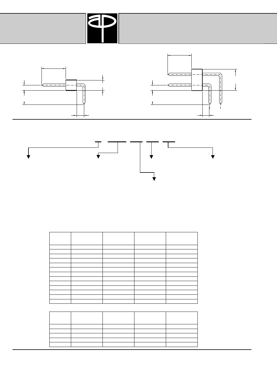
2,54 mm Male Headers
Series 235L
D
B
6 mm
(Typ.)
C
6 mm
(Typ.)
C
2,50 mm
5,00 mm
D
B
Ordering Information
9x8xxx-xx-xx-xx
Product Option:
1 Row Plating Options:
Contact Quantity per Row Plating Suffix
3 = High Temperature Product
835 = Solder Plating
1 to 36
none =
Standard Product
without Kinked Tail
648 = Selective Gold / Solder plating
10 =
0,25 µm sel. Au Plating
648 = all over Gold plating
SnPb30 Solder Tails
K = High Temperature Product
15 =
0,25 µm sel. Au Plating
with Kinked Tail as
2 Row Plating Options:
Pin Length Identifier
with Sn100 Solder Tails
Board Retention Feature
838 = Solder Plating
Please see table below
20 =
0,50 µm sel. Au Plating
667 = Selective Gold / Solder plating
SnPb30 Solder Tails
667 = all over Gold plating
25 =
0,76 µm sel. Au Plating
with Sn100 Solder Tails
30 =
0,76 µm sel. Au Plating
SnPb30 Solder Tails
35 =
0,76 µm sel. Au Plating
Sn100 Solder Tails
50 =
Sn100 Solder Plating
Pin Length Identifier Table (1 Row):
Indicator
Dimension
B
(Solder Tail)
Dimension
C
(Bend)
Dimension
D
(Distance to Board)
Dimension
Interface
01
2,84 mm
1,80 mm
1,20 mm
6,00 mm
10
3,60 mm
1,80 mm
1,20 mm
6,00 mm
11
4,50 mm
1,80 mm
1,20 mm
6,00 mm
02
10,50 mm
1,80 mm
1,20 mm
6,00 mm
03
15,54 mm
1,80 mm
1,20 mm
6,00 mm
04
5,76 mm
4,34 mm
1,20 mm
6,00 mm
12
6,56 mm
4,34 mm
1,20 mm
6,00 mm
13
7,36 mm
4,34 mm
1,20 mm
6,00 mm
07
8,13 mm
4,34 mm
1,20 mm
6,00 mm
05
13,21 mm
4,34 mm
1,20 mm
6,00 mm
08
15,76 mm
4,34 mm
1,20 mm
6,00 mm
06
18,26 mm
4,34 mm
1,20 mm
6,00 mm
09
20,76 mm
4,34 mm
1,20 mm
6,00 mm
Pin Length Identifier Table (2 Row):
Indicator
Dimension
B
(Solder Tail)
Dimension
C
(Bend)
Dimension
D
(Distance to Board)
Dimension
Interface
01
2,84 mm
1,80 mm
1,20 mm
6,00 mm
04
3,60 mm
1,80 mm
1,20 mm
6,00 mm
05
4,50 mm
1,80 mm
1,20 mm
6,00 mm
02
10,50 mm
1,80 mm
1,20 mm
6,00 mm
03
15,54 mm
1,80 mm
1,20 mm
6,00 mm
Engineering Note:
The information presented in this
datasheet is accurate to the best of
our knowledge.
Due to ongoing efforts to advance
design and material performance,
this information is subject to change
without notice.