Assembly – Bosch GGS 6 S Professional User Manual
Page 16
16 | English
1 619 929 K88 | (26.4.12)
Bosch Power Tools
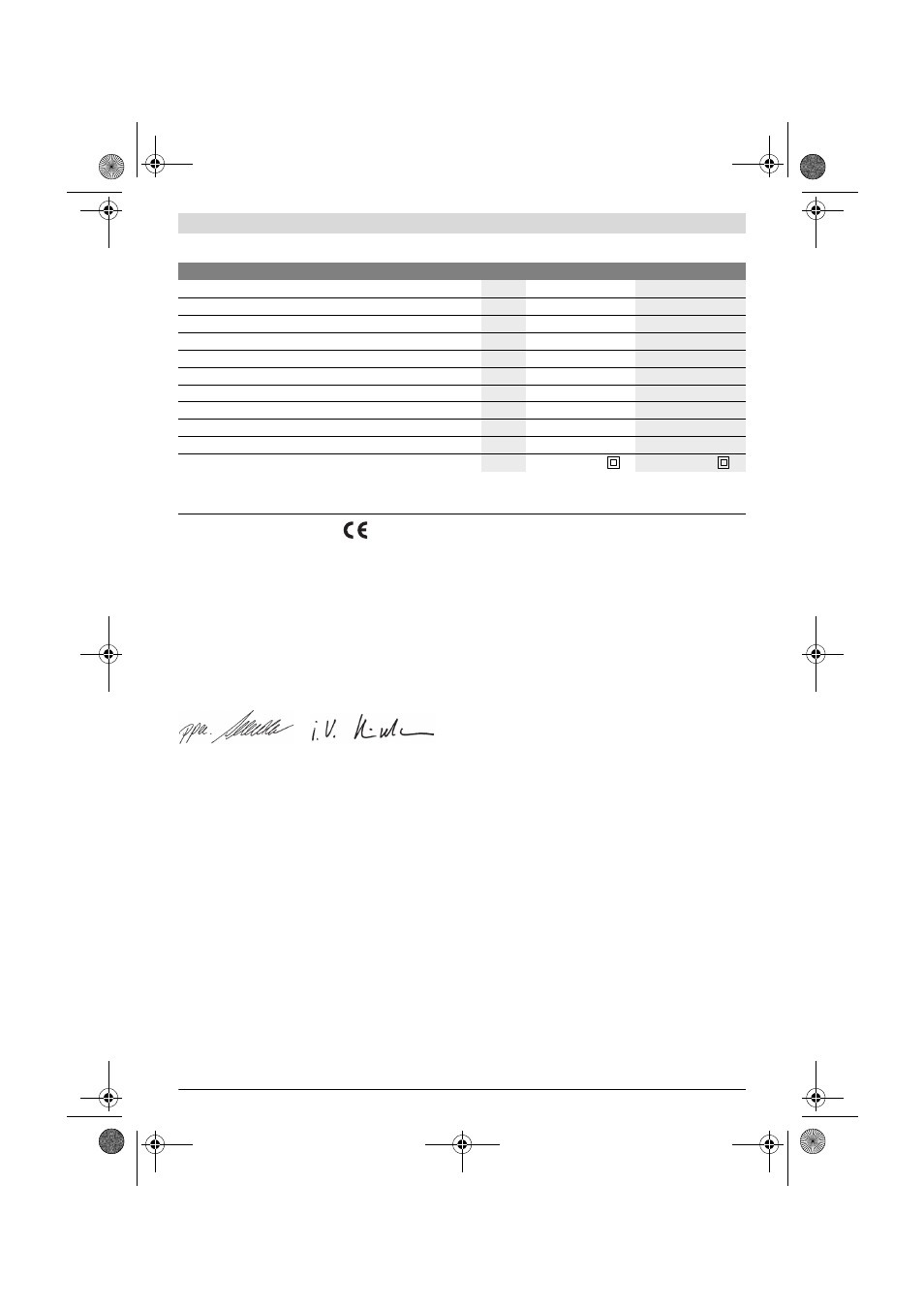
Technical Data
Declaration of Conformity
We declare under our sole responsibility that the product de-
scribed under “Technical Data” is in conformity with the fol-
lowing standards or standardization documents: EN 60745
according to the provisions of the directives 2011/65/EU,
2004/108/EC, 2006/42/EC.
Technical file (2006/42/EC) at:
Robert Bosch GmbH, PT/ETM9,
D-70745 Leinfelden-Echterdingen
Robert Bosch GmbH, Power Tools Division
D-70745 Leinfelden-Echterdingen
28.03.2012
Assembly
f
Before any work on the machine itself, pull the mains
plug.
Mounting the Protective Devices
f
Adjust protection guards in such a manner that spark-
ing toward the operator is prevented.
Protection Guard for Grinding (GGS 6 S) (see figure A)
Place the protection guard 2 on the spindle collar. Adapt the
position of the protection guard 2 to the requirements of the
work step. Lock the protection guard 2 with locking screw 14
and tighten the locking screw with at least 10 Nm.
Protection Guard for Grinding (GGS 6) (see figure E)
Place the protection guard 11 on the spindle collar. Adapt the
position of the protection guard 11 to the requirements of the
work step. Lock the protection guard 11 with the two locking
nuts 19 and tighten the locking nuts with at least 10 Nm.
After mounting the grinding tool, shut the protection guard 11
and tighten both wing nuts.
Mounting the Grinding Tools
The grinding tools must run completely concentrically. Do not
continue to use damaged grinding tools that are out of bal-
ance. If the grinding tools are out of balance they should be re-
placed. Treat with a whetstone (accessory) or change.
Using a whetstone, any particular special shape can be pro-
duced out of the basic forms of the grinding accessory.
When using grinding tools with a threaded insert, pay atten-
tion that the end of the grinder spindle 3 does not touch the
hole base of the grinding tool.
GGS 6 S (see figure B)
– Turn the grinder spindle 3 until the hole in the grinder spin-
dle 3 and the openings of the housing are aligned. Insert
the holding rod 15 through the openings of the housing
and the hole of the grinder spindle 3.
– Loosen and remove the clamping nut 1 with the two-pin
spanner 16 provided.
– Clean the grinder spindle 3 and all parts to be mounted.
– Mount the grinding accessory and tighten clamping nut 1
with two-pin spanner 16. Pay attention that the grinding
accessory can rotate freely in protection guard 2.
f
Use tapered grinding accessories only in conjunction
with the open protection guard 2 and the matching
clamping system (clamping nut 1 and mounting flange
4).
GGS 6 (see figure F)
– Turn the grinder spindle 3 until the hole in the grinder spin-
dle 3 and the openings of the housing are aligned. Insert
the holding rod 15 through the openings of the housing
and the hole of the grinder spindle 3.
– Loosen the clamping nut 9 with the open-end spanner 20
(size 24 mm) by turning in anticlockwise direction.
– Remove the clamping flange 10.
– Clean the grinder spindle 3 and all parts to be mounted.
Straight grinder
GGS 6
GGS 6 S
Article number
0 601 214 0..
0 601 214 1..
Rated power input
W
1200
1150
Output power
W
720
670
Max. speed
min
-1
6800
6800
Thread of grinder spindle
5/8"
M 14
Max. spindle length
mm
27
31
Tool holder
mm
16
20
Max. grinding disc thickness
mm
25
32
Grinding tool diameter, max.
mm
125
125
Weight according to EPTA-Procedure 01/2003
kg
3.9
3.9
Protection class
/II
/II
The values given are valid for a nominal voltage [U] of 230 V. For different voltages and models for specific countries, these values can vary.
Starting cycles generate brief voltage drops. Interference with other equipment/machines may occur in case of unfavourable mains system conditions.
Malfunctions are not to be expected for system impedances below 0.36 ohm.
Dr. Egbert Schneider
Senior Vice President
Engineering
Helmut Heinzelmann
Head of Product Certification
PT/ETM9
OBJ_BUCH-1050-004.book Page 16 Thursday, April 26, 2012 10:22 AM