Garmin GNS 430 User Manual
Page 44
GNS 430(A) Pilot’s Guide and Reference
190-00140-00 Rev. P
SECTION 3
NAV PAGES
3-10
Table 3-4 lists the settings available for each group:
Group
Available Settings
Map
Orientation, AutoZoom, Land Data,
Aviation Data
Weather
Lightning Mode/Symbol
(when applicable)
Traffic
Traffic Mode/Symbol/Label
(when applicable)
Airport
Large/Medium/Small Airports and
Text
NAVAID
VORs, NDBs, Intersections, and Text
Waypoint
User Waypoints, Waypoint Text,
Flight Plan Wpts
Line
Active Flight Plan, Lat/Long
Control
Controlled Airspace: Class B, C, D
(tower zone)
Airspace
Special-Use Airspace: Restricted,
MOA, Other
City
Large/Medium/Small Cities and Text
Road
Freeway, National Highway, Local
Hwy, Local Road
Other
States/Prov, Rivers/Lakes, Railroads,
Wind Vector
Table 3-4
For most entries in Table 3-4, on, off, and range are the
available selections for display of each information type.
NOTE: Large, medium, and small classifications
are used on the GNS 430 for airports and cities.
Large airports are those with a runway longer
than 8100 feet. Medium airports include those
with a runway longer than 5000 feet or with
a control tower. Large cities are those with
approximate populations greater than 200,000
and medium cities with greater than 50,000.
To change map orientation:
1) From the Map Page Menu, turn the large right
knob to highlight ‘Setup Map?’ (Figure 3-16)
and press the ENT Key.
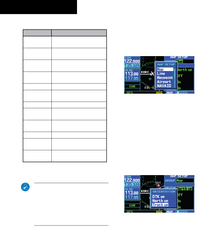
2) Turn the small right knob to select ‘Map’
(Figure 3-17) and press the ENT Key.
Figure 3-17 Map Setup Window
3) Turn the large right knob to highlight the
‘Orientation’ field.
4) Turn the small right knob to select the desired
option.
a) Select ‘DTK up’ to fix the top of the Map Display
to the desired course.
b) Select ‘North up’ to fix the top of the Map
Display to a north heading.
c) Select ‘Track up’ (Figure 3-18) to adjust the
top of the Map Display to the current track
heading.
Figure 3-18 Orientation Window