Pc 5150, Pc 5192 – Acnodes PC 5192 User Manual
Page 42
© Copyright 2009 Acnodes, Inc.
All rights reserved. Product description and product specifications
are subject to change without notice. For latest product information,
please visit Acnodes’ web site at
PC 5150
15-inch touch panel PC
42
PC 5192
19-inch sunlight readable touch panel PC
661 Brea Canyon Rd., Suite 3
Walnut, CA 91789
tel: 909.598.7388, fax: 909.598.0218,
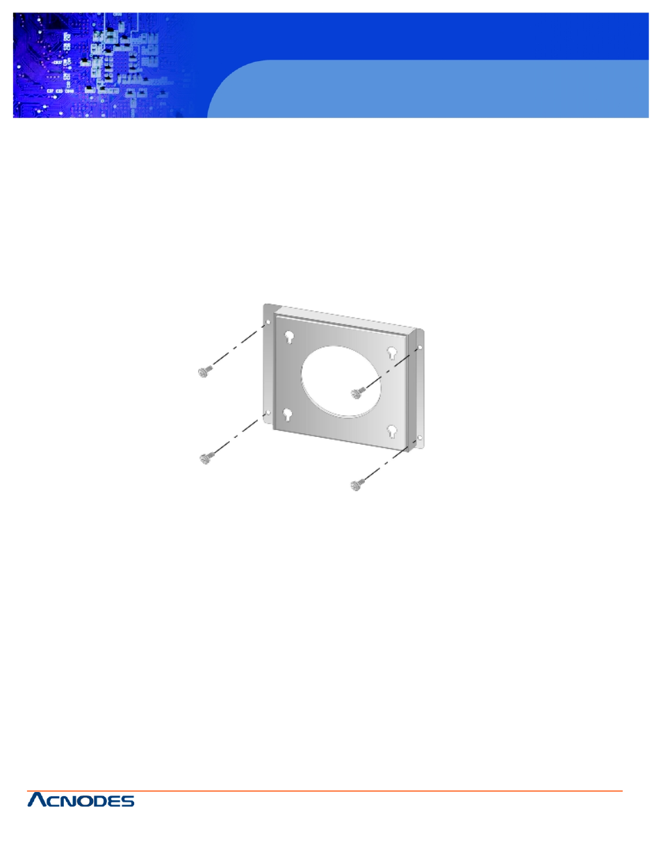
4.7.1 Wall Mounting
To mount the PC 5192 flat panel PC onto a wall, please follow the steps below.
Step 1: Select the location on the wall for the wall-mounting bracket.
Step 2: Carefully mark the locations of the four bracket screw holes on the wall.
Step 3: Drill four pilot holes at the marked locations on the wall for the bracket retention screws.
Step 4: Align the wall-mounting bracket screw holes with the pilot holes.
Step 5: Secure the mounting-bracket to the wall by inserting the retention screws into the four pilot holes and tightening them
(see Figure 3-11).
Figure 4-15: Wall-mounting Bracket
Step 6: Insert the four monitor mounting screws provided in the wall mounting kit into the four screw holes on the real panel of
the monitor and tighten until the screw shank is secured against the rear panel (see Figure 3-12).
Step 7: Align the mounting screws on the monitor rear panel with the mounting holes on the bracket.
Step 8: Carefully insert the screws through the holes and gently pull the monitor downwards until the monitor rests securely in
the slotted holes (see Figure 3-12). Ensure that all four of the mounting screws fit snuggly into their respective slotted holes.
NOTE: In the diagram below the bracket is already installed on the wall.