Rmc 7152, Pc 5192 – Acnodes PC 5192 User Manual
Page 103
661 Brea Canyon Rd., Suite 3
Walnut, CA 91789
tel: 909.598.7388, fax: 909.598.0218, www.acnodes.com
© Copyright 2009 Acnodes, Inc.
All rights reserved. Product description and product specifications
are subject to change without notice. For latest product information,
please visit Acnodes’ web site at
RMC 7152
14” short depth server
RMC 7152
14” short depth server
103
PC 5192
19-inch sunlight readable touch panel PC
7.6.2 Install the New PSU
Installation is done in the reverse order to removal. To install a new PSU module, please follow the steps below.
Step 1: Attach the PSU bracket to the PSU module with the previously removed retention screws.
Step 2: Insert the PSU module and bracket assembly into the chassis and attach the PSU bracket to the chassis with the
previously removed retention screws.
Step 3: Secure the PSU module to the chassis by reinserting the previously removed retention screws through the bottom
panel.
Step 4: Bundle the cables of the new PSU module and secure them with a plastic tie similar to the old PSU module.
Step 5: Reconnect all previously disconnected power connectors to the motherboard and disk drives.
Step 6: Reattach the elevated platform.
Step 7: Replace the back cover.
7.7 System Cooling Fan Replacement
If the system cooling fans have been damaged, they must be replaced. To replace the system cooling fans, please follow the
steps below.
7.7.1 Remove the Old System Cooling Fans
Step 1: Remove the back cover (Section 4.4).
Step 2: Detach and remove the elevated platform (Section 7.5).
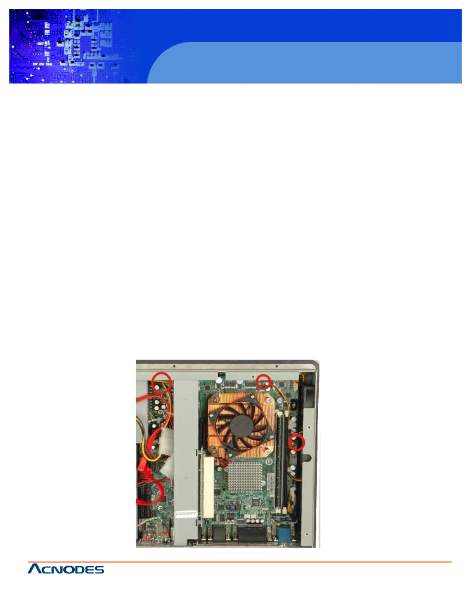
Step 3: Disconnect the system cooling fans from the motherboard (Figure 7-9).
Figure 7-9: System Cooling Fans Motherboard Connector