Figure 5, Table 4, Ng to each section of – 3Com V7111 User Manual
Page 17: Table 5
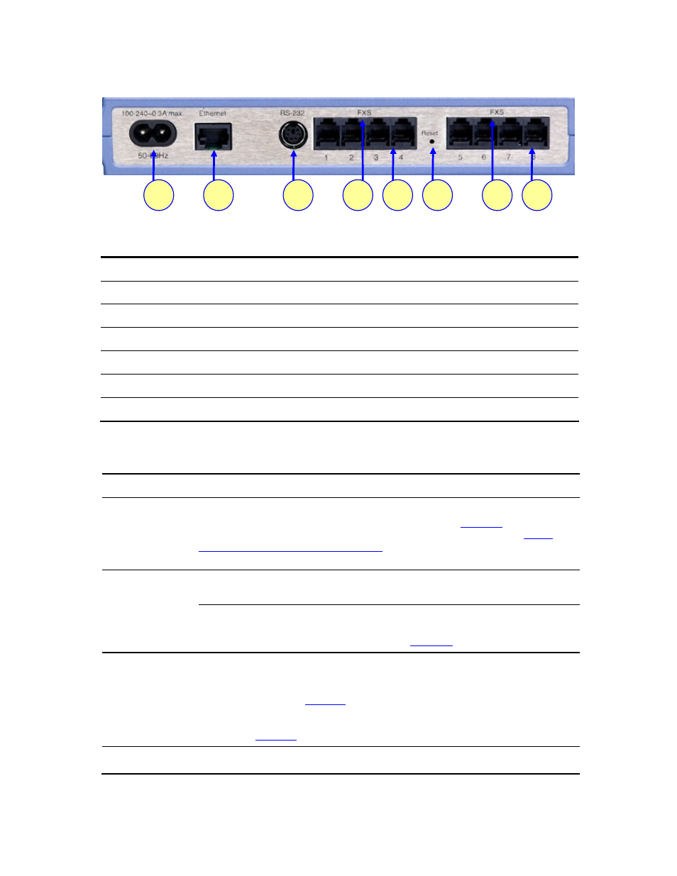
Figure 5
V7111 Rear Panel Connectors
1
2
3
4
4
5
6
5
Table 4
V7111 Rear Panel Component Descriptions
Item #
Label
Component Description
1
100-240~0.3A max.
AC power supply socket
2
Ethernet
10/100 Base-TX Uplink port
3
RS-232
RS-232 status port (requires a DB-9 to PS/2 adaptor)
4
FXS or FXO
A label that distinguishes between FXS & FXO devices
5
--
2, 4 or 8 FXS / FXO ports
6 Reset
Reset
button
Table 5
V7111 Cables and Cabling Procedure
Cable Cabling
Procedure
Connect the Ethernet connection on the V7111 directly to the network using a
standard RJ-45 Ethernet cable. For connector pinouts, see
RJ-45 Ethernet
cable
.
Note that when assigning an IP address to the V7111 using HTTP (under
Assigning an IP Address Using HTTP
), you may be required to disconnect this
cable and re-cable it differently.
Connect the RJ-11 FXS connectors to fax
machines, modems, or phones.
Ensure that FXS and FXO ports are
connected to the correct devices,
RJ-11 two-wire
telephone cords
otherwise damage can occur.
The RJ-11 pinouts are described in
Connect the RJ-11 FXO connectors to
telephone exchange analog lines or PBX
extensions.
Using a standard RS-232 straight cable (not a cross-over cable) with DB-9
connectors, connect the V7111 RS-232 port (using a DB-9 to PS/2 adaptor) to either
COM1 or COM2 RS-232 communication port on your PC. The pinouts of the PS/2
connector are shown in
RS-232 serial
cable
.
A PS/2 to DB-9 adaptor is not included with the V7111 package. For the PS/2 to DB-9
pinouts, see
Connect the V7111 power socket to the mains.
AC Power cable
3Com VCX V7111 Analog Gateway Installation Guide
17