Phasing, Blower rotation, Belt tension – York PREDATOR 150 User Manual
Page 24: 22 belt adjustment, 16 supply air limitations
035-17311-002-A-0803
24
Unitary Products Group
PHASING
Predator
®
units are properly phased at the factory. Check for
proper compressor rotation. If the blower or compressors
rotate in the wrong direction at start-up, the electrical connec-
tion to the unit is misphased. Change the phasing of the Field
Line Connection at the factory or field supplied discon-
nect to obtain proper rotation. (Scroll compressors operate in
only one direction. If the scroll is drawing low amperage, has
similar suction and discharge pressures, or producing a high
noise level, the scroll is misphased.)
BLOWER ROTATION
Check for proper supply air blower rotation. If the blower is
rotating backwards, the line voltage at the unit point of power
connection is misphased (See ‘PHASING’).
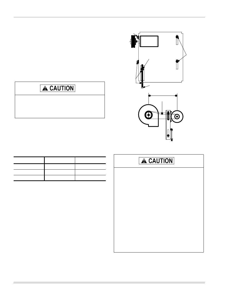
BELT TENSION
The tension on the belt should be adjusted as shown in
Figure 22.
Scroll compressors require proper rotation to oper-
ate correctly. Units are properly phased at the fac-
tory. Do not change the internal wiring to make the
blower condenser fans, or compressor rotate cor-
rectly.
TABLE 16: SUPPLY AIR LIMITATIONS
Unit Size
Minimum
Maximum
090
2250
3750
120
3000
5000
150
3750
6250
FIGURE 22 - BELT ADJUSTMENT
Procedure for adjusting belt tension:
1. Loosen six nuts (top and bottom) A.
2. Adjust by turning (B).
3. Never loosen nuts (C).
4. Use belt tension checker to apply a perpendicular
force to one belt at the midpoint of the span as
shown. Deflection distance of 4mm (5/32”) is
obtained.
To determine the deflection distance from normal
position, use a straight edge from sheave to sheave
as reference line. The recommended deflection
force is as follows:
Tension new belts at the max. deflection force rec-
ommended for the belt section. Check the belt ten-
sion at least two times during the first 24 hours of
operation. Any retensioning should fall between the
min. and max. deflection force values.
5. After adjusting retighten nuts (A).
A
A
A
B
SPAN LENGTH
DEFL. FORCE
C*
* NEVER LOOSEN