Location, Rigging and handling, Predator – York PREDATOR 150 User Manual
Page 11: Unit voltage limitations, Unit temperature limitations, Figure 4 - predator, Component location, Table 1: unit voltage limitations, Table 2: unit temperature limitations
035-17311-002-A-0803
Unitary Products Group
11
LOCATION
Use the following guidelines to select a suitable location for
these units:
1.
Unit is designed for outdoor installation only.
2.
Condenser coils must have an unlimited supply of air.
Where a choice of location is possible, position the unit
on either north or east side of building.
3.
Suitable for mounting on roof curb.
4.
For ground level installation, use a level concrete slab
with a minimum thickness of 4 inches. The length and
width should be at least 6 inches greater than the unit
base rails. Do not tie slab to the building foundation.
5.
Roof structures must be able to support the weight of the
unit and its options/accessories. Unit must be installed
on a solid, level roof curb or appropriate angle iron
frame.
6.
Maintain level tolerance to 1/2” across the entire width
and length of unit.
RIGGING AND HANDLING
Exercise care when moving the unit. Do not remove any
packaging until the unit is near the place of installation. Rig
the unit by attaching chain or cable slings to the lifting holes
provided in the base rails. Spreader bars, whose length
exceeds the largest dimension across the unit, MUST be
used across the top of the unit.
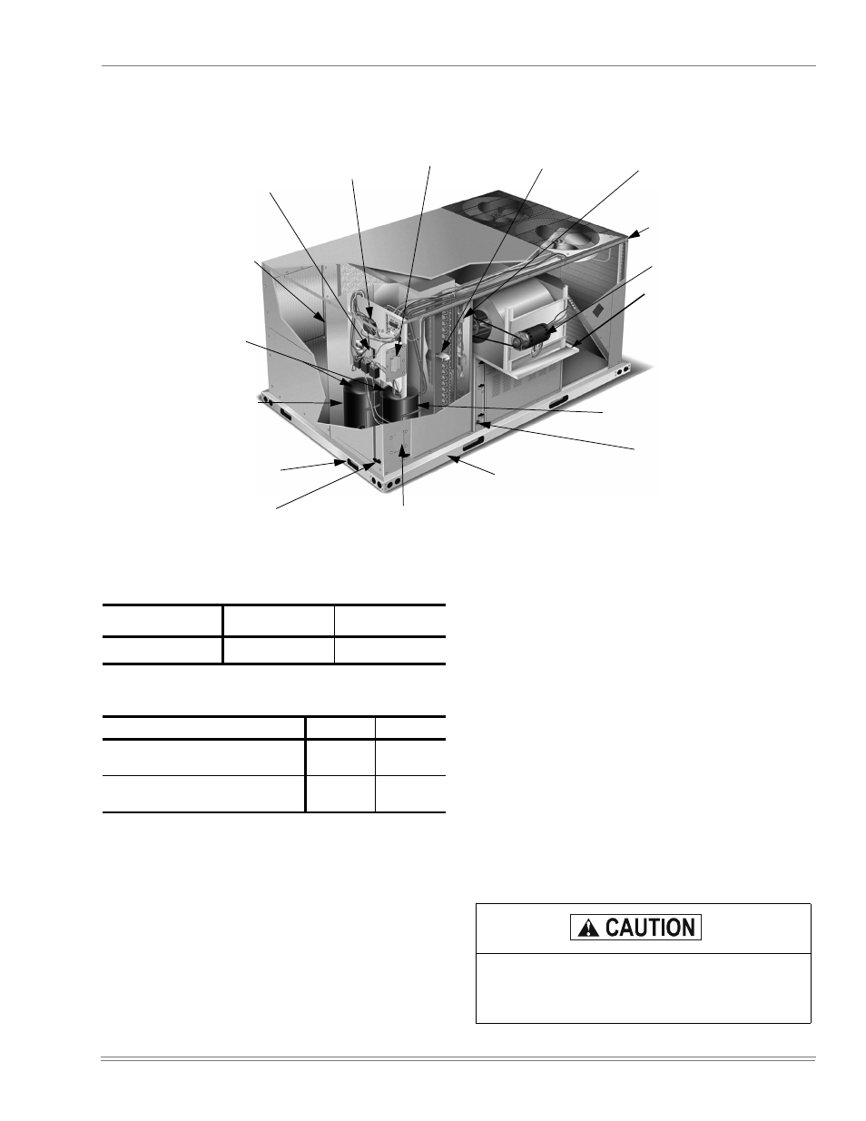
FIGURE 4 - PREDATOR
®
COMPONENT LOCATION
Tool-less door
latch
Side entry power
and control wiring
knockouts
Disconnect location
(optional disconnect switch)
Filter access (2” throw-away)
Roof curbs in eight- and fourteen-inch
heights. Roof curbs for transitioning from
York Sunline™ footprint to the DM
Series footprint are also available
(field-installed accessory)
Slide-out drain pan
with steel 3/4” FPT
connection
Compressor #1 access (high-
efficiency compressor w/
crankcase heater))
Belt-drive
blower motor
Filter drier (solid
core)
Condenser
section
Base rails w/fork-
lift slots (3 sides)
and lifting holes)
Compressor #2
access (high-
efficiency com-
pressor with
crankcase heater
Dual stage
cooling for
max. comfort
Terminal block for
hi-voltage connection
Second model name-
plate inside hinged
access panel
Slideout motor
& blower
assembly for
easy access
adjustment &
service
Simplicity™ Control board
w/screw connector
for T-stat wiring and
network connection
TABLE 1:
UNIT VOLTAGE LIMITATIONS
Power Rating
Minimum
Maximum
380
350
418
TABLE 2:
UNIT TEMPERATURE LIMITATIONS
Temperature
Min.
Max.
Wet Bulb Temperature (
°
F) of Air on
Evaporator Coil
57
72
Dry Bulb Temperature (
°
F) of Air on
Condenser Coil
0
*
*.
A low ambient accessory is available for operation
down to -20°F.
125
If a unit is to be installed on a roof curb other than a
YORK roof curb, gasketing must be applied to all
surfaces that come in contact with the unit under-
side.