York PREDATOR DR120 User Manual
Page 11
127878-YIM-B-0606
Unitary Products Group
11
LOCATION
Use the following guidelines to select a suitable location for
these units:
1.
Unit is designed for outdoor installation only.
2.
Condenser coils must have an unlimited supply of air.
Where a choice of location is possible, position the unit
on either north or east side of building.
3.
Suitable for mounting on roof curb.
4.
For ground level installation, use a level concrete slab
with a minimum thickness of 4 inches. The length and
width should be at least 6 inches greater than the unit
base rails. Do not tie slab to the building foundation.
5.
Roof structures must be able to support the weight of the
unit and its options/accessories. Unit must be installed on
a solid, level roof curb or appropriate angle iron frame.
6.
Maintain level tolerance to 1/2” across the entire width
and length of unit.
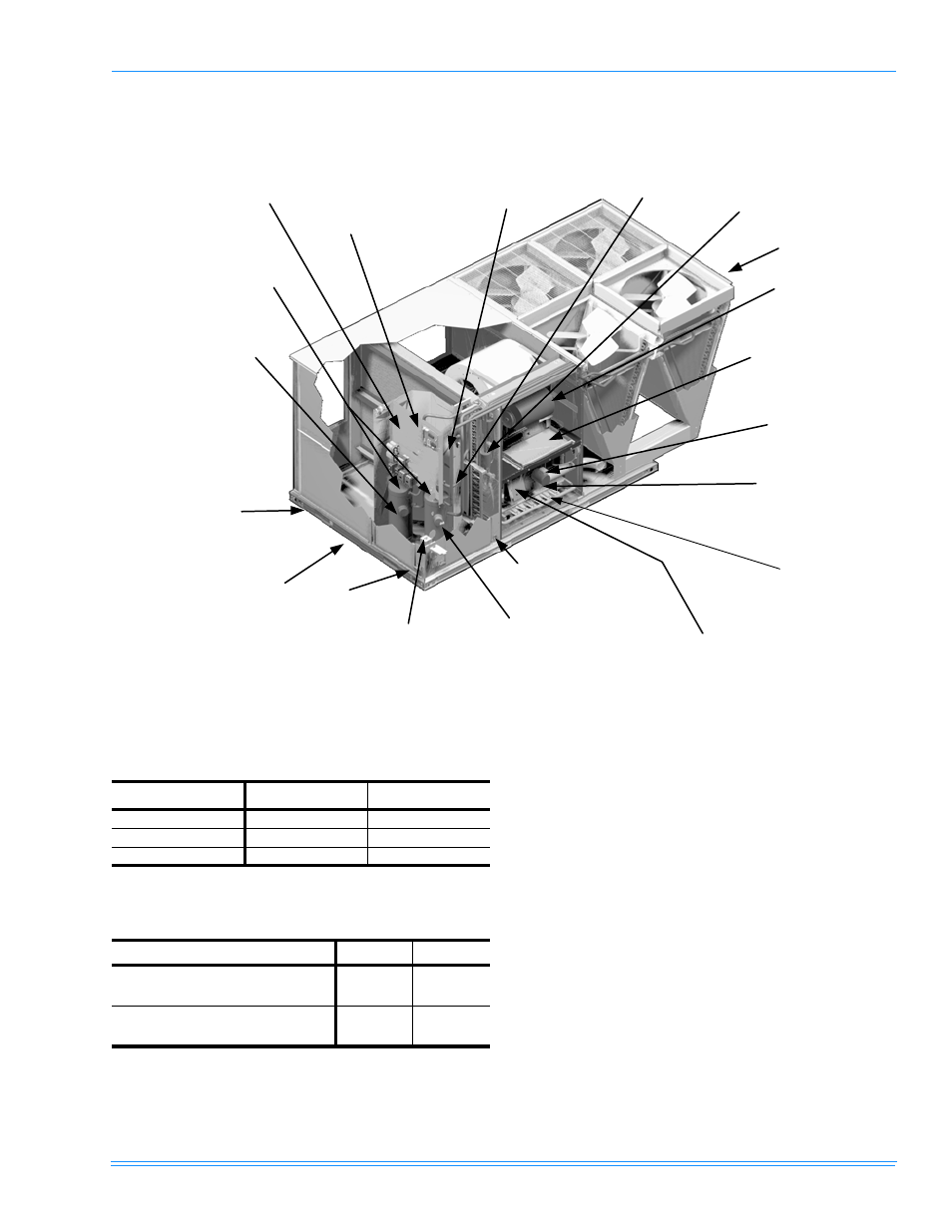
FIGURE 5 -
PREDATOR MagnaDRY™ DR150 COMPONENT LOCATION
Simplicity™ Control
board w/screw
connectors for T-stat
wiring and Network
Connection
Disconnect
location (optional
disconnect switch)
Filter access
(2" throw-away)
Filter drier (solid core)
Condenser Section
Belt-drive blower
motor
Slide out motor
and blower
assembly for easy
adjustment and
service
Power ventor
motor
20-gauge
aluminized steel
tubular heat
exchanger for
long life
(stainless steel
option)
Two-stage gas heating to
maintain warm,
comfortable temperature
Intelligent control
board for safe and
efficient operation
Slide-out drain pan
with brass ¾" NPT,
female connection
Compressor #1 access
(high-efficiency
compressor w/crankcase
heater)
Side entry power
and control wiring
knockouts
Tool-less door
latch
Roof curbs in eight-and
fourteen-inch heights.
Roof curbs for
transitioning from York
Sunline TM footprint to
the DM/DH/DJ Series
footprint are available
(field-installed accessory)
Base rails w/
forklift slots
( three sides)
and lifting
holes
Compressor #2
access
(high-efficiency
compressor w/
crankcase heater)
Dual stage cooling
for maximum
comfort
Second model
nameplate inside
hinged access panel
TABLE 1:
UNIT VOLTAGE LIMITATIONS
Power Rating
*
*.
Utilization range “A” in accordance with ARI Standard 110.
Minimum
Maximum
208/230-3-60
187
252
460-3-60
432
504
575-3-60
540
630
TABLE 2:
UNIT TEMPERATURE LIMITATIONS
Temperature
Min.
Max.
Wet Bulb Temperature (
°F) of Air on
Evaporator Coil
57
72
Dry Bulb Temperature (
°F) of Air on
Condenser Coil
0
*
*.
A low ambient accessory is available for operation
down to -20°F.
125