Refrigerant piping connections, Fixing and piping, Maximum piping length – York YUHC 18-60 User Manual
Page 15
15
ENGLISH
■
Fixing and Piping
• Piping must be performed by qualified personnel
according to good refrigeration system practices.
• Piping materials and insulation materials must be of
refrigerant quality.
• Select the pipe diameters according to the size of
unit and cut the pipe to design length by using pipe
cutter.
• Install the flare nuts and flare the end of the pipes.
• Check that no foreign bodies are inside the piping.
• Align the central of the connection pipes and tighten
the flare nut.
• Fix piping with pipe clamps and check that any pipe
vibrations cannot be transmitted to the building
structure.
• Connect the pipe correctly.
• Do not apply the excessive torque.
• Use an appropriate bending tool to form curves and
avoid over-tightening the refrigerant tubes.
• To prevent heat loss, the two lines must be insulated
separately.
■
Maximum Piping Length
The suction line must have a 2% gradient up to the
compressor on horizontal sections.
Where piping lengths are unusually long and include a
large number of oil traps, it may be necessary to adjust
to compressor charge.
NOTES
Unit size
18
24
30
36
48
60
(m)
30
30
30
30
30
30
REFRIGERANT PIPING CONNECTIONS
■
Refrigerant charge to be added per extra
meter of piping length when more than 5
meters.
Prefabricated refrigerant piping is available as an acces-
sory. If this is not used, piping and insulating materials
employed must be compatible with this type of installa-
tion.
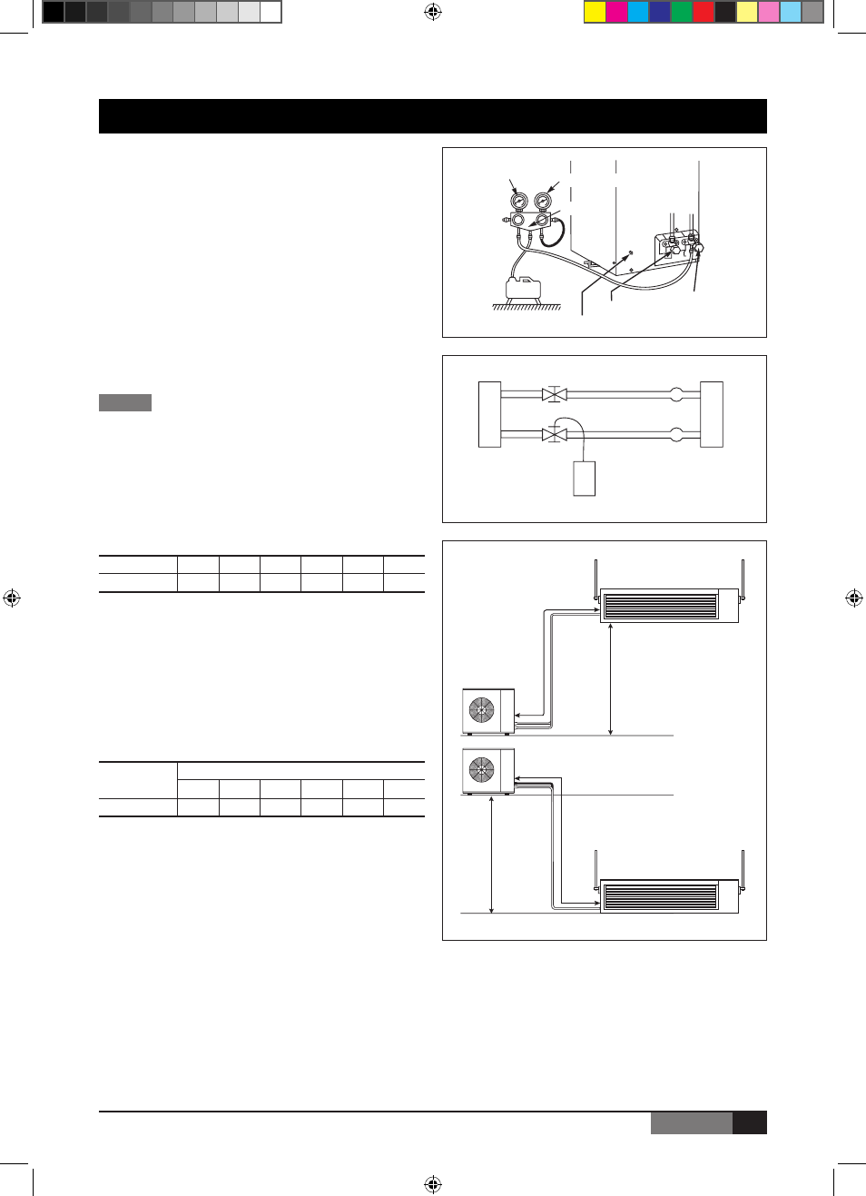
The pre-charged outdoor unit does not require charging
if piping length is 5 m or less. However, the interconnect-
ing piping and the indoor unit must be pumped down
before releasing R-410A refrigerant into them from the
outdoor unit.
1. Remove the cap from the service valve.
2. Connect the line to a vacuum pump and pump
down to 5 Pa.
3. When pump down is finished, wait 15 minutes
to detect potential circuit leakage. Open service
valves on the outdoor unit.
Outdoor unit
Indoor unit
Gas line
Liquid line
R-410A
*
Note: The expansion device is located in the outdoor unit.
High pressure
Pressure tap
Manifold
Low pressure
Liquid valve
Gas valve
L
D
L
H
Unit size
Models
18
24
30
36
48
60
(g/m)
30
65
90
90
90
90
J368-EN.indd 15
2/1/07 9:41:19 AM