Figure 2 - unit component location – York AFFINITY 292443-XTG-B-0807 User Manual
Page 5
292443-XTG-B-0807
Unitary Products Group
5
required if Thermostat 2ET07700224 and 2ET04700224 are
used.
MOTORIZED FRESH AIR DAMPER - Designed for duct
mounted side supply/return and unit mounted down supply/
return applications. Damper capable of providing 0% through
50% of outdoor air (field supplied). Closes on power loss,
includes hood and screen assembly.
FILTER / FRAME KIT (Single Phase only) - Kit contains the
necessary hardware to field install return air filters into the
base unit. Pre-cut filter racks and appropriate cleanable stan-
dard size filters are shipped in one kit. The fiter rack is suit-
able for either 1” or 2” filters (1” filter is supplied). This kit is
available for single phase horizontal or vertical duct applica-
tion only. Standard in all 3 phase models
RECTANGLE TO ROUND ADAPTERS - Kit includes one
supply and one return air rectangle to round duct adapter.
Adapters are preformed and designed to fit over current duct
openings on the base unit. Transition is from side square duct
opening to 14" round duct opening.
ROOF CURBS - NRCA approved curbs provide proper fit to
base unit for rooftop installations. Curbs are designed to be
assembled through hinge pins in each corner. Kit also pro-
vides seal strip to assure a water tight seal. 8 and 14 inch
high roof curbs are available.
MANUAL OUTDOOR DAMPER - Provides 0% through 50%
outdoor air capability (field adjustable). Designed for duct
mounted side supply/return applications. Includes hood and
screen assembly.
WALL THERMOSTAT - The units are designed to operate
with 24-volt electronic and electro-mechanical thermostats.
All units can operate with single stage heat / single stage cool
thermostats - with or without the economizer.
LOW AMBIENT KIT - Kit provides necessary hardware to
convert unit to operate in cooling cycle down to 0 F. Standard
unit operation 45 F.
TRANSFORMER KIT - Kit provides necessary hardware to pro-
vide single phase models from factory furnished 40 VA trans-
former capability to 75 VA transformer capability. (Required on
installations with economizer or motorized damper.)
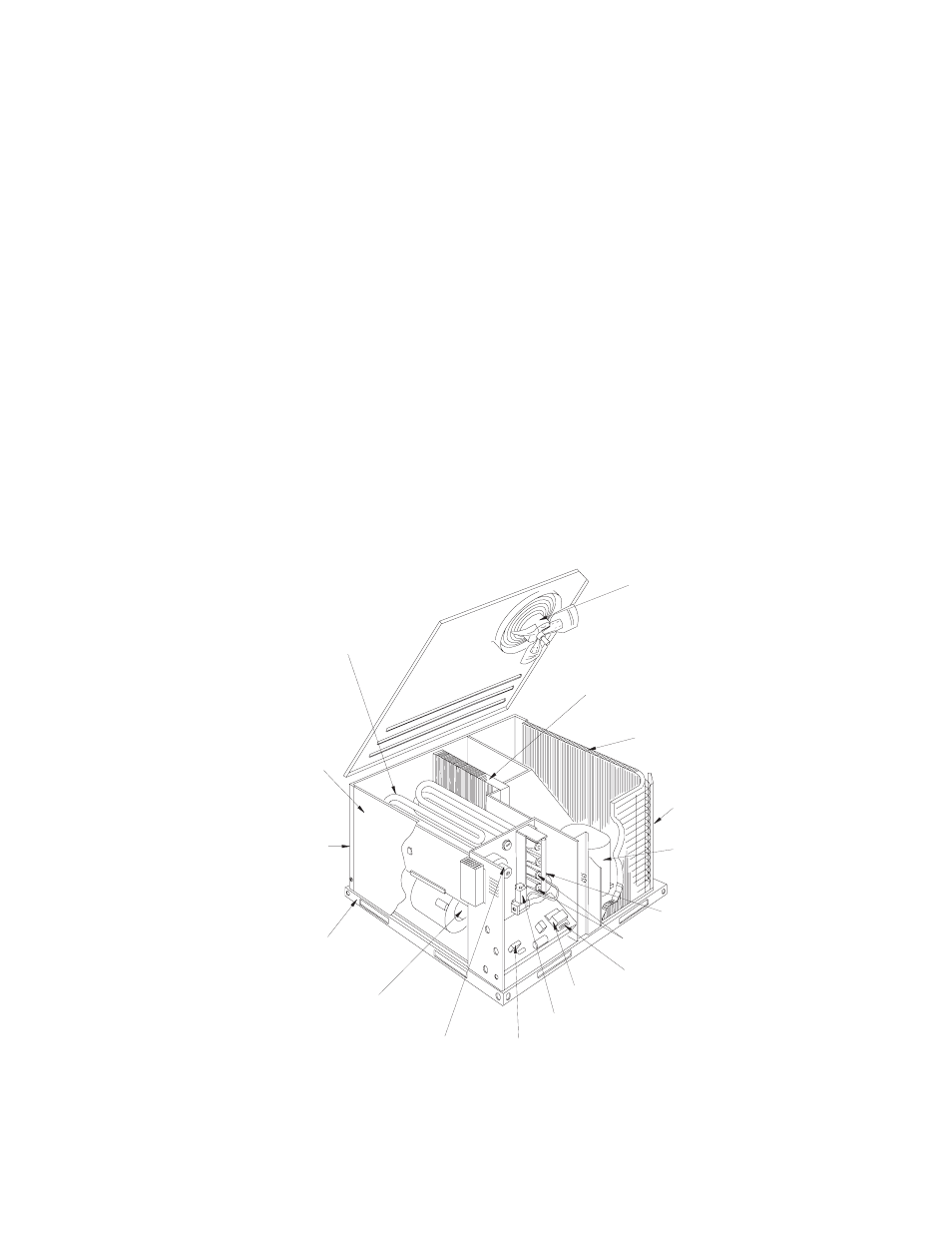
FIGURE 2 - UNIT COMPONENT LOCATION
BLOW-THROUGH DESIGN
WITH RELIABLE ALUMINIZED
STEEL TUBULAR HEAT
EXCHANGERS
LONG-LASTING
POWDER PAINT
FINISH
REAR & BOTTOM
RETURN AIR
AND SUPPLY AIR
DUCT OPENINGS
HEAVY GAUGE
REMOVEABLE
BASE RAILS
3-SPEED DIRECT DRIVE
BLOWER MOTOR WITH
SLIDE-OUT BLOWER ASSEMBLY
POWER VENTER MOTOR
HIGH VOLTAGE
TERMINAL BLOCK
AUTOMATIC
GAS VALVE
(1/2"- 14NPTI)
SELF-DIAGNOSTIC CONTROLS
WITH "COMFORT MATCH" SPEED
CONTROL
LOW VOLTAGE
TERMINAL BLOCK
HIGH GRADE
ALUMINIZED
IN-SHOT BURNERS
PILOT ASSEMBLY
HIGH EFFICIENCY
COMPRESSOR
RIGIDLY MOUNTED
DECORATIVE
PROTECTIVE
COIL GUARD
HIGHLY EFFICIENT
ENHANCED COPPER
TUBE/ALUMINUM FIN
CONDENSER COIL
HIGHLY EFFICIENT
ENHANCER
COPPER TUBE/ALUMINUM FIN
EVAPORATOR COIL
DIRECT DRIVE
CONDENSER FAN
MOTOR