York 13 SEER - R410A CZB018 THRU 060 User Manual
Page 2
246723-YTG-J-1006
2
Unitary Products Group
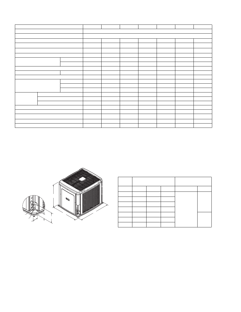
All dimensions are in inches. They are subject to change without
notice. Certified dimensions will be provided upon request.
PHYSICAL AND ELECTRICAL DATA
MODEL
CZB01811
CZB02411
CZB03011
CZB03611
CZB04211
CZB04811
CZB06011
Unit Supply Voltage
208-230V, 1
φ, 60Hz
Normal Voltage Range
1
187 to 252
Minimum Circuit Ampacity
13.3
16.5
18.9
22.3
28.7
27.9
34.4
Max. Overcurrent Device Amps
2
20
25
30
35
50
45
60
Min. Overcurrent Device Amps
3
15
20
20
25
30
30
35
Compressor Type
Scroll
Scroll
Scroll
Scroll
Scroll
Scroll
Scroll
Compressor Amps
Rated Load
10.3
14.3
16.4
16.6
21.8
21.1
26.3
Locked Rotor
51
60
73
88
105
113
150
Crankcase Heater
No
No
No
No
No
No
No
Fan Motor Amps
Rated Load
0.5
0.5
0.5
1.5
1.5
1.5
1.5
Fan Diameter Inches
22
22
22
22
22
22
22
Fan Motor
Rated HP
1/15
1/15
1/15
1/4
1/4
1/4
1/4
Nominal RPM
850
850
850
850
850
850
850
Nominal CFM
2100
2,250
2,300
3,200
3,250
3,500
3,500
Coil
Face Area Sq. Ft.
14.86
14.86
17.15
17.15
20.58
20.58
20.58
Rows Deep
1
1
1
1
1
1
2
Fins / Inch
22
22
22
22
22
22
22
Liquid Line Set OD (Field Installed)
3/8
3/8
3/8
3/8
3/8
3/8
3/8
Vapor Line Set OD (Field Installed)
3/4
3/4
3/4
3/4
7/8
7/8
7/8
Unit Charge (Lbs. - Oz.)
4
5-13
6-4
7-4
6-4
8-13
8-12
13-9
Charge Per Foot, Oz.
0.62
0.62
0.62
0.62
0.67
0.67
0.67
Operating Weight Lbs.
165
170
190
190
205
215
260
1
Rated in accordance with ARI Standard 110, utilization range “A”.
2
Dual element fuses or HACR circuit breaker. Maximum allowable overcurrent protection.
3
Dual element fuses or HACR circuit breaker. Minimum recommended overcurrent protection.
4
The Unit Charge is correct for the outdoor unit, matched indoor coil and 15 feet of refrigerant tubing. For tubing lengths other than
15 feet, add or subtract the amount of refrigerant, using the difference in length multiplied by the per foot value.
VAPOR
LIQUID
2-3/8
3-1/8
6-1/2
C
A
B
DIMENSIONS
Unit
Model
Dimensions
(Inches)
Refrigerant Connection
Service Valve Size
A
B
C
Liquid
Vapor
018
29-1/2
37
31
3/8”
3/4”
024
29-1/2
37
31
030
33-1/2
37
31
036
33-1/2
37
31
042
39-1/2
37
31
7/8”
048
39-1/2
37
31
060
39-1/2
37
31