York GF9S*DH User Manual
Page 20
268890-UIM-B-0607
20
Unitary Products Group
The combustion air intake pipe should be located either through the
wall (horizontal or side vent) or through the roof (vertical vent). Care
should be taken to locate side vented systems where trees or shrubs
will not block or restrict supply air from entering the terminal.
Also, the terminal assembly should be located as far as possible from a
swimming pool or a location where swimming pool chemicals might be
stored. Be sure the terminal assembly follows the outdoor clearances
listed in Section #1 “COMBUSTION AIR QUALITY (LIST OF CONTAM-
INANTS).”
Fresh air pipe can either be routed through the furnace or routed out-
side the furnace.
Ambient Combustion Air Supply
This type installation will draw the air required for combustion from
within the space surrounding the appliance and from areas or rooms
adjacent to the space surrounding the appliance. This may be from
within the space in a non-confined location or it may be brought into the
furnace area from outdoors through permanent openings or ducts. It is
not piped directly into the burner box. A single, properly sized pipe from
the furnace vent connector to the outdoors must be provided. For down-
flow models combustion air is brought into the furnace through the unit
top panel opening. Do not install a pipe into the combustion air pipe at
the top of the furnace. Refer to Figures 19 & 26.
An unconfined space is not less than 50 cu.ft (1.42 m
3
) per 1,000 Btu/
hr. (0.2928 kW) input rating for all of the appliances installed in that
area.
Rooms communicating directly with the space containing the appli-
ances are considered part of the unconfined space, if openings are not
furnished with doors.
A confined space is an area with less than 50 cu.ft (1.42 m
3
) per 1,000
Btu/hr. (0.2928 kW) input rating for all of the appliances installed in that
area. The following must be considered to obtain proper air for combus-
tion and ventilation in confined spaces.
Combustion Air Source From Outdoors
The blocking effects of louvers, grilles and screens must be given con-
sideration in calculating free area. If the free area of a specific louver or
grille is not known, refer to Table 12, to estimate free area.
*
Do not use less than 1/4” (0.635 cm) mesh
+
Free area or louvers and grilles varies widely; the installer should follow lou-
ver or grilles
manufacturer’s instructions.
Dampers, Louvers and Grilles (Canada Only)
1.
The free area of a supply air opening shall be calculated by sub-
tracting the blockage area of all fixed louvers grilles or screens
from the gross area of the opening.
2.
Apertures in a fixed louver, a grilles, or screen shall have no
dimension smaller than 0.25” (0.64 cm).
3.
A manually operated damper or manually adjustable louvers are
not permitted for use.
4.
A automatically operated damper or automatically adjustable lou-
vers shall be interlocked so that the main burner cannot operate
unless either the damper or the louver is in the fully open position.
This type of installation requires that the supply air to the appli-
ance(s) be of a sufficient amount to support all of the appliance(s)
in the area. Operation of a mechanical exhaust, such as an exhaust
fan, kitchen ventilation system, clothes dryer or fireplace may cre-
ate conditions requiring special attention to avoid unsatisfactory
operation of gas appliances. A venting problem or a lack of supply
air will result in a hazardous condition, which can cause the appli-
ance to soot and generate dangerous levels of CARBON MONOX-
IDE, which can lead to serious injury, property damage and / or
death.
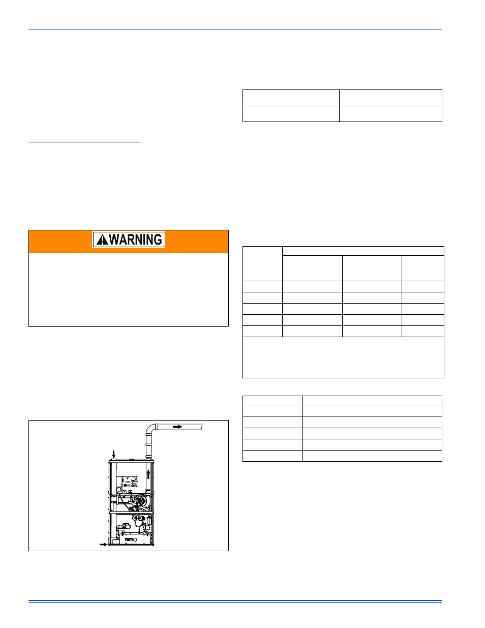
FIGURE 26: Combustion Airflow Path Through The Furnace Casing to
the Burner Box
VENT PIPE PASSES
THROUGH TOP PANEL
COMBUSTION AIRFLOW
3-WAY TRANSITION
COMBUSTION
AIRFLOW
TABLE 12: Estimated Free Area
Wood or Metal
Louvers or Grilles
Wood 20-25%*
Metal 60-70% *
Screens+
1/4” (0.635 cm)
mesh or larger 100%
TABLE 13: Free Area - Outdoor Air
BTUH Input
Rating
Minimum Free Area Required for Each Opening
Horizontal Duct
(2,000 BTUH)
Vertical Duct or
Opening to Outside
(4,000 BTUH)
Round Duct
(4,000
BTUH)
40,000
20 sq. in. (129 cm
2
)
10 sq. in. (65 cm
2
)
4” (10 cm)
60,000
30 sq. in. (194 cm
2
)
15 sq. in. (97 cm
2
)
5” (13 cm)
80,000
40 sq. in. (258 cm
2
) 20 sq. in. (129 cm
2
)
5” (13 cm)
100,000
50 sq. in. (323 cm
2
) 25 sq. in. (161 cm
2
)
6” (15 cm)
120,000
60 sq. in. (387 cm
2
) 30 sq. in. (194 cm
2
)
7” (18 cm)
EXAMPLE: Determining Free Area.
Appliance 1Appliance
2Total
Input
100,000
+ 30,000 = (130,000
÷ 4,000) = 32.5 Sq. In. Vertical
Appliance 1Appliance
2Total
Input
100,000
+ 30,000 = (130,000
÷ 2,000) = 65 Sq. In. Horizontal
TABLE 14: Unconfined Space Minimum Area in Square Inches
BTUH Input Rating
Minimum Free Area Required for Each Opening
40,000
40 (258 cm
2
)
60,000
60 (387 cm
2
)
80,000
80 (516 cm
2
)
100,000
100 (645 cm
2
)
120,000
120 (774 cm
2
)