York GF9S*DH User Manual
Page 10
268890-UIM-B-0607
10
Unitary Products Group
SECTION V: ELECTRICAL POWER
ELECTRICAL POWER CONNECTIONS
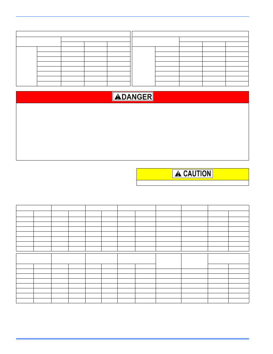
Field wiring to the unit must be grounded. Electric wires that are field
installed shall conform to the temperature limitation for 63°F (35°C) rise
wire when installed in accordance with instructions. Refer to Table 7 in
these instructions for specific furnace electrical data.
Annual Fuel Utilization Efficiency (AFUE) numbers are determined in accordance with DOE Test procedures.
Wire size and over current protection must comply with the National Electrical Code (NFPA-70-latest edition) and all local codes.
The furnace shall be installed so that the electrical components are protected from water.
NOTES:
1. For altitudes above 2000 ft. (609 m) reduce capacity 4% for each 1000 ft. above sea level.
2. Wire size based on copper conductors, 140° F (60°C), 3% voltage drop.
3. Continuous return air temperature must not be below 55°F (12.8° C).
TABLE 6: Nominal Manifold Pressure
Manifold Pressures (in wc)
Manifold Pressures (kpa)
Altitude (feet)
Altitude (m)
0-7999
8000-8999
9000-9999
0-2437
2438-2742
2743-3048
G
a
s H
eating
V
a
lue
(BTU/cu f
t.)
800
3.5
3.5
3.5
G
a
s H
eating
V
a
lue
(MJ/cu m)
29.8
0.87
0.87
0.87
850
3.5
3.5
3.5
31.7
0.87
0.87
0.87
900
3.5
3.5
3.5
33.5
0.87
0.87
0.87
950
3.5
3.5
3.3
35.4
0.87
0.87
0.81
1000
3.5
3.2
2.9
37.3
0.87
0.80
0.73
1050
3.5
2.9
2.7
39.1
0.87
0.73
0.67
1100
3.2
2.7
2.4
41.0
0.80
0.66
0.61
2500 (LP)
9.8
8.2
7.5
93.2 (LP)
2.44
2.03
1.86
PROPANE AND HIGH ALTITUDE CONVERSION KITS
It is very important to choose the correct kit and/or gas orifices for the altitude and the type of gas for which the furnace is being installed.
Only use natural gas in furnaces designed for natural gas. Only use propane (LP) gas for furnaces that have been properly converted to use pro-
pane (LP) gas. Do not use this furnace with butane gas.
Incorrect gas orifices or a furnace that has been improperly converted will create an extremely dangerous condition resulting in premature heat
exchanger failure, excessive sooting, high levels of carbon monoxide, personal injury, property damage, a fire hazard and/or death.
High altitude and propane (LP) conversions are required in order for the appliance to satisfactory meet the application.
An authorized distributor or dealer must make all gas conversions.
In Canada, a certified conversion station or other qualified agency, using factory specified and/or approved parts, must perform the conversion.
The installer must take every precaution to insure that the furnace has been converted to the proper gas orifice size when the furnace is installed.
Do not attempt to drill out any orifices to obtain the proper orifice size. Drilling out a gas orifice will cause misalignment of the burner flames,
causing premature heat exchanger burnout, high levels of carbon monoxide, excessive sooting, a fire hazard, personal injury, property damage
and/or death.
Use copper conductors only.
TABLE 7: Electrical and Performance Data
Input/Cabinet
Output
Nominal Airflow
Cabinet Width
Total Unit
AFUE
Air Temp. Rise
MBH
kW
MBH
kW
CFM
m
3
/min
In.
mm
Amps
%
°F
°C
40/A
12
37
10.8
1200
34
14-1/2
368
9
94
35 - 65
19 - 36
60/B
18
55
16.1
1200
34.0
17-1/2
444
9
92
35 - 65
19 - 36
80/B
23
74
21.7
1200
34.0
17-1/2
444
9
92
35 - 65
19 - 36
80/C
23
74
21.7
1600
45.3
21
533
12
92
35 - 65
19 - 36
100/C
29
93
27.3
1600
45.3
21
533
12
92
35 - 65
19 - 36
100/C
29
93
27.3
2000
56.6
21
533
14
92
35 - 65
19 - 36
120/D
35
112
32.8
2000
56.6
24-1/2
622
14
92
35 - 65
19 - 36
Input/Cabinet
Max. Outlet
Air Temp.
Blower
Blower Size
Max.
Over-current
Protect
Min. Wire Size
(awg) @ 75 ft.
One Way
Operation
Weight
MBH kW
°F
°C
HP
Amps
In.
cm
Lbs.
Kg.
40/A
12
165
73.9
1/2
7.0
11 x 8
27.9 x 20.3
20
14
120
54.5
60/B
18
165
73.9
1/2
7.0
11 x 8
27.9 x 20.3
20
14
130
59.0
80/B
23
165
73.9
1/2
7.0
11 x 8
27.9 x 20.3
20
14
145
65.9
80/C
23
165
73.9
3/4
10.2
11 x 10
27.9 x 25.4
20
14
155
70.5
100/C
29
165
73.9
3/4
10.2
11 x 10
25.4 x 25.4
20
14
170
77.3
100/C
29
165
73.9
1
12.7
11 x 11
27.9 x 27.9
20
12
175
79.5
120/D
35
165
73.9
1
12.7
11 x 11
27.9 x 27.9
20
12
180
81.8