Static resistances, 10 electric heater cfm limitations – York DF 072 User Manual
Page 11
254599-YTG-C-0807
Unitary Products Group
11
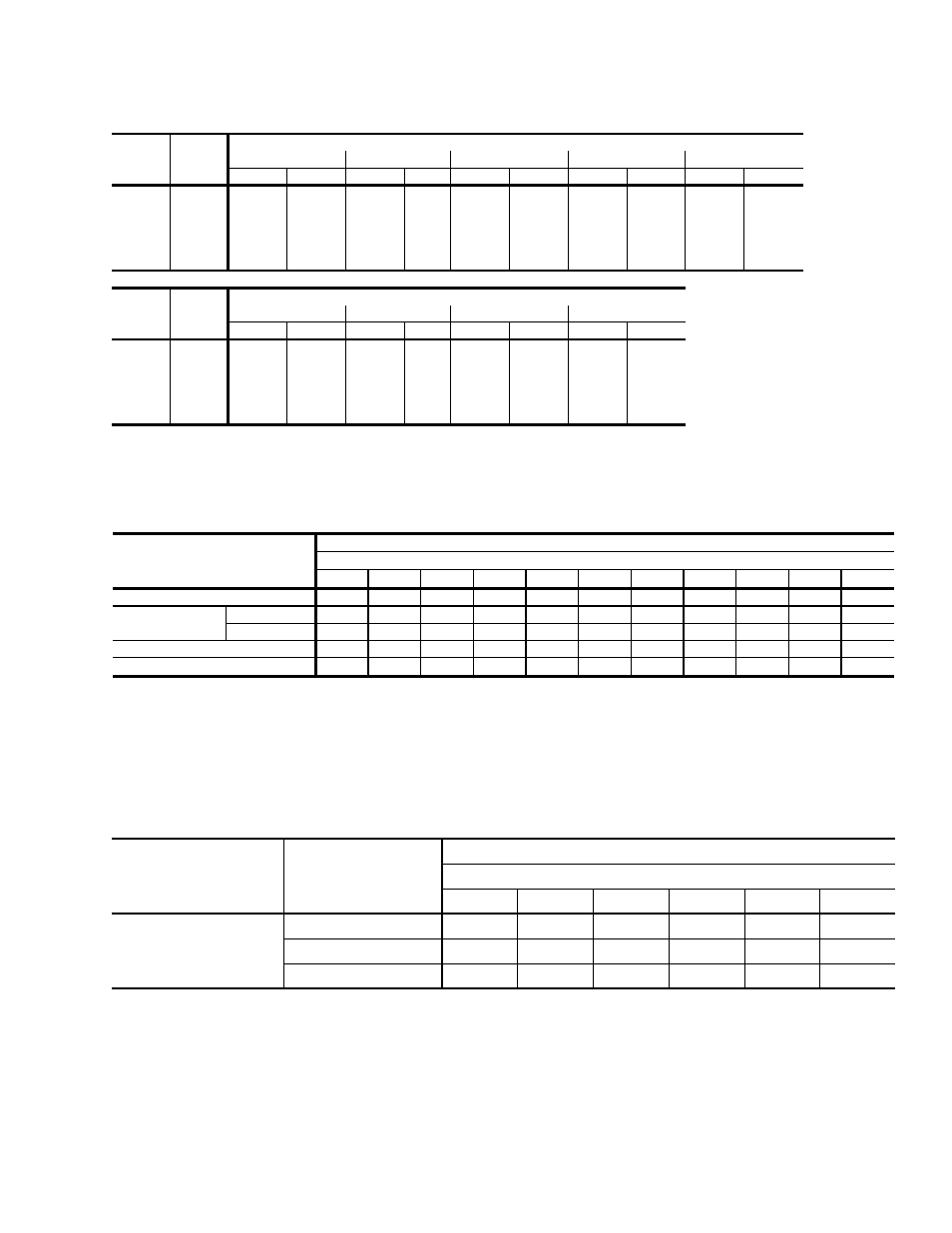
TABLE 8: SUPPLY AIR BLOWER PERFORMANCE (6 TON BELT DRIVE) - SIDE DUCT APPLICATION
Unit
Tonnage
Motor
Speed
Available External Static Pressure - IWG
1
1. Includes allowances for a wet evaporator coil, 1” filters, and the heat exchangers. Refer to STATIC RESISTANCES
Table for resistance values.
0.2
0.3
0.4
0.5
0.6
CFM
Watts
CFM
Watts
CFM
Watts
CFM
Watts
CFM
Watts
6
2
2. Side Duct application (230 Volts)
Hi
2256
883
2258
931
2247
950
2223
964
2182
979
Med/Hi
2145
771
2127
784
2119
808
2089
826
2051
844
Med
2020
637
1999
656
1985
675
1947
696
1910
715
Med/Low
-
-
-
-
-
-
-
-
-
-
Low
-
-
-
-
-
-
-
-
-
-
Unit
Tonnage
Motor
Speed
Available External Static Pressure - IWG
0.7
0.8
0.9
1.0
CFM
Watts
CFM
Watts
CFM
Watts
CFM
Watts
6
Hi
2125
971
2044
940
1958
898
1864
854
Med/Hi
2014
859
1965
861
1896
843
1801
806
Med
1876
730
1832
740
1793
756
-
-
Med/Low
-
-
-
-
-
-
-
-
Low
-
-
-
-
-
-
-
-
TABLE 9: STATIC RESISTANCES
1000
1200
1400
1600
1800
2000
2200
2400
2600
2800
3000
0.07
0.08
0.09
0.11
0.13
0.15
0.17
0.20
0.23
0.26
0.30
7-15KW
0.04
0.05
0.06
0.07
0.08
0.10
0.12
0.14
0.16
0.19
0.22
20-30KW
0.06
0.07
0.08
0.09
0.11
0.13
0.15
0.17
0.20
0.23
0.26
0.06
0.07
0.08
0.09
0.10
0.11
0.12
0.14
0.16
0.19
0.22
0.08
0.10
0.12
0.14
0.16
0.18
0.20
0.23
0.26
0.29
0.32
COOLING ONLY
2
RESISTANCE, IWG
CFM
DESCRIPTION
ECONOMIZER
1 3
BOTTOM DUCT CONNECTIONS
1
ELECTRIC
HEATERS
1
1. Deduct these resistance values from the available external static pressure shown in SUPPLY AIR BLOWER PERFORMANCE Tables.
3. The pressure through the economizer is greater for 100% outdoor air than for 100% return air. If the resistance of the return air
duct system is less than 0.25 IWG, the unit will deliver less CFM during full economizer operation.
2. Add these resistance values to the available static resistance values on SUPPLY AIR BLOWER PERFORMANCE Tables.
TABLE 10: ELECTRIC HEATER CFM LIMITATIONS
UNIT MODEL SIZE NOMI-
NAL TONS
VOLTAGE
MINIMUM SUPPLY AIR CFM
HEATER SIZE NOMINAL KW
5
7
10
15
20
30
6
208/230-3-60
1800
1800
1800
1800
1800
1800
460-3-60
-
1800
1800
1800
1800
1800
575-3-60
-
-
1800
1800
1800
1800