5connection – Toshiba IK - HD1C User Manual
Page 9
9
㽽 DC IN 12V terminal
Accept a DC power input (12V).
㽾 Y/G terminal
Outputs Y or G. (BNC connector)
㽿 P
B
/B terminal
Outputs P
B
or B. (BNC connector)
㾀 P
R
/R terminal
Outputs P
R
or R. (BNC connector)
㾁 REMOTE terminal
To connect to a RS-232C device for remote control function.
㾂 EXT. SYNC terminal
Used when the camera output signal is synchronized to an external signal.
(BNC connector)
㾃 SYNC OUT terminal
Output terminal for synchronization signal. (BNC connector)
㾄 HD-SDI terminal
Video signal output terminal for HD-SDI format video signal. (BNC connector)
㾅 KEY LOCK switch
Enables/disables buttons
FORMAT switch
Switches between 59.94i and 60i.
㽵 to 㽼.
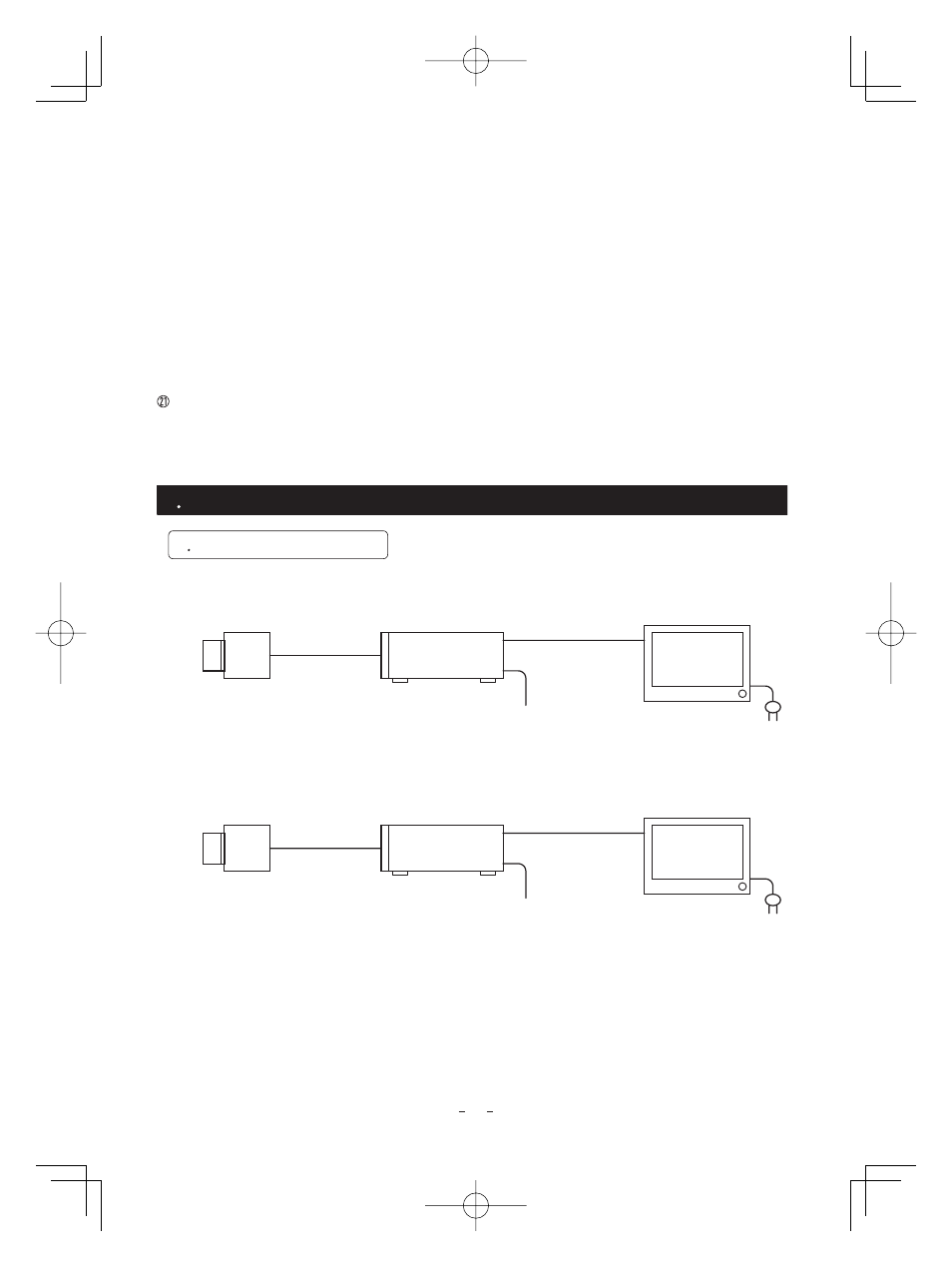
Lens
(option)
IK-HD1H
䋨option䋩
Camera
Control unit
Camera Cable
for IK-HD1C
䋨option䋩
HD monitor
analog TV (option)
DC power supply
(option)
DC power supply
(option)
DC IN 12V
Y/P
B
/P
R
Three Coaxial
Cables 75
(option)
㱅
IK-HD1C
5
CONNECTION
5
5. 1 -1 Analog Connection
1 Standard Connection
Lens
(option)
IK-HD1H
䋨option䋩
Camera
Control unit
Camera Cable
for IK-HD1C
䋨option䋩
HD monitor
digital TV (option)
DC IN 12V
HD-SDI
One Coaxial
Cable 75
(option)
㱅
IK-HD1C
5. 1 -2 Digital Connection
* Please use a low conductor resistance cable for HD-SDI terminal.