Toshiba IK - HD1C User Manual
Page 10
10
DC IN 12V
1 +12V
2 +12V
3 GND
4 GND
REMOTE
1
2
3
4
5
6
7
8
9 NC
NC
NC
NC
GND
NC
RXD
TXD
NC
5
3A Connector Pin Assignments
䊶 Only use optional camera head model # IK-HD1H with this camera controller.
The use of another head may cause damage to the control unit and camera head.
䊶 When connecting the camera cables, be sure to turn off the camera control unit and
any other equipment connected to it.
䊶 For DC power supply connecting to DC IN 12V terminal, use UL listed and/or CSA
approved ungrounded type AC adaptor with the specifications described below.
Power supply voltage
䋺 12V DC 㫧10%
Current rating
䋺 More than 830mA, Less than2.5A
Ripple voltage
䋺 Less than 50mV (p-p)
Connector
䋺 HR10A-7P-4S by HIROSE electronics Co. Ltd
Pins 1, 2
䋺 12V
Pins 3, 4
䋺 GND
䊶 If the securing screw on the connector of the camera cable loosens, noise may appear
on the screen. Be sure to tighten the connector completely.
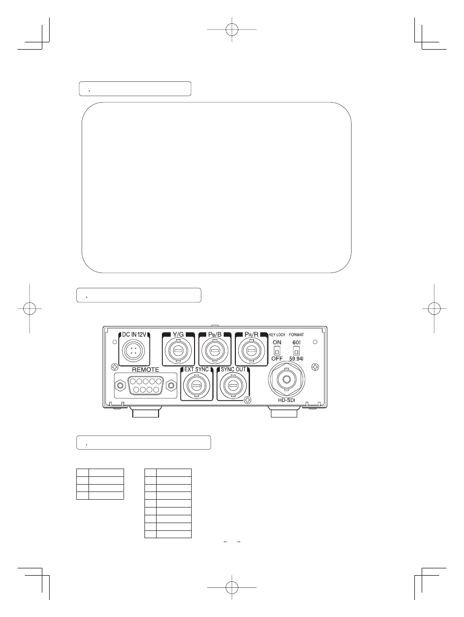
Back panel view
5
2 Caution on Connection
5
3 Connection on Back Panel
3
4
2
1
1 2 3 4 5
8
7
9
6