Connecting hydraulic control tubing, System start-up, Warning – Toro 730 User Manual
Page 3
Connecting Hydraulic Control Tubing
1. Route control tubing from controller to sprinkler
location(s).
NOTE:
❚
Leave an 18" (45.7 cm) service loop of tubing at each
sprinkler to facilitate movement of sprinkler and
service operations.
❚
Tubing runs in excess of 1,000' (304.8 m) are not
advisable due to delayed response time.
❚
The valve elevation for normally open valve-in-head
systems should not exceed 25' (7.6 m) above
controller elevation or 70' (21.3 m) below controller
elevation.
❚
The valve elevation for normally closed valve-in-head
systems should not exceed 0' above controller
elevation or 70' (21.3 m) below controller elevation.
❚
If connecting more than one VIH sprinkler per control
tubing run, refer to the chart below.
2. Flush tubing thoroughly to remove all air and debris.
3. Remove tube retainer and poly cap from tubing
adapter at base of sprinkler.
4. Slide tube retainer over control tubing and attach tubing to adapter.
5. Slide tube retainer over adapter area to secure tubing.
System Start-Up
The following is a recommended procedure that will protect system components during system start-up. The procedure is based on a
velocity fill rate of less than 2' (0.6 m) per second. See Table 2 below.
1. Use jockey pump only to fill system at velocity fill rate of less than 2' (0.6 m) per second.
2. Use quick coupler keys at all tees and greens with quick coupler valves to bleed air from system lines during filling process. Do
not compress air and then relieve, bleed air while filling system.
3. After water has filled all lines and all air is removed, remove quick coupler keys.
CAUTION
Failure to comply with recommended fill rate will increase line pressure resulting in a water hammer effect
that could damage sprinklers and/or piping system.
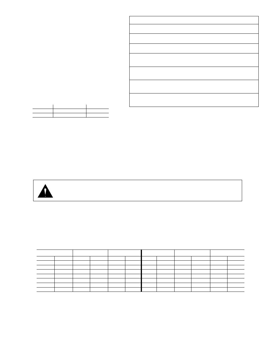
Table 2:
Recommended System Fill Rate
WARNING
DUE TO HIGH OPERATING PRESSURE, NEVER STAND OR LEAN DIRECTLY OVER TOP OF
SPRINKLER OR COME IN CONTACT WITH SPRAY. FAILURE TO COMPLY MAY RESULT IN
SERIOUS INJURY.
3
Recommended
Maximum
1" VIH
3
5
1.5" VIH
2
3
Table 2: Control
Systems
Maximum Distance
Type of System*
From Controller
Elevation Restrictions
Pin-type
£
(00) Hydraulic*
with
3
⁄
16
" Control Tubing
100'
Pin-type
£
(00) Hydraulic*
with
1
⁄
4
" Control Tubing
200'
Normally Open (01)
Valve elevation should not exceed
with
3
⁄
16
" Control Tubing
500'
25' ABOVE controller elevation or
70' BELOW controller elevation.
Normally Closed (08)
Valve elevation should not exceed
with
3
⁄
16
" Control Tubing
500'
0' ABOVE controller elevation or
70' BELOW controller elevation.
Normally Open (01)
Valve elevation should not exceed
with
1
⁄
4
" Control Tubing
1000'
25' ABOVE controller elevation or
70' BELOW controller elevation.
Normally Closed (08)
Valve elevation should not exceed
with
1
⁄
4
" Control Tubing
1000'
0' ABOVE controller elevation or
70' BELOW controller elevation.
Pipe Size
Flow
Velocity
Pipe Size
Flow
Velocity
in.
cm
GPM
LPM
ft/sec
m/sec
in.
cm
GPM
LPM
ft/sec
m/sec
1/2
1.3
2
7.6
1.60
0.49
3
7.6
45
170.3
1.86
0.57
3/4
1.9
3
11.4
1.92
0.59
4
10.2
75
283.9
1.87
0.57
1
2.5
5
18.9
1.50
0.46
6
15.2
150
567.8
1.73
0.53
1-1/4
3.2
10
37.9
1.86
0.57
8
20.2
250
946.3
1.70
0.52
1-1/2
3.8
10
37.9
1.41
0.43
10
25.4
450
1703.3
1.97
0.60
2
5.0
20
75.7
1.80
0.55
12
30.5
500
1892.5
1.55
0.47
2-1/2
6.4
30
113.6
1.84
0.56
* - All hydraulic connections on Toro valves are
1
⁄
4
" insert type.
- Control line pressure must be equal to or 10% greater than mainline pressure.
- Control line pressure range is 40 to 150 PSI
£
NOTE: Maximum of one (1) valve pr station on pin-type systems.