2 battery and breaker diagrams, Diagrams, Continued) – Tripp Lite Extended-Run Single-Phase Battery Cabinet User Manual
Page 12
12
Shelf 2
Shelf 3
Shelf 1 (Bottom)
To Fuse or Breaker
Termination
To UPS
Positive
To UPS
Negative
UL-Listed
Breaker
Battery
Positive
Battery
Negative
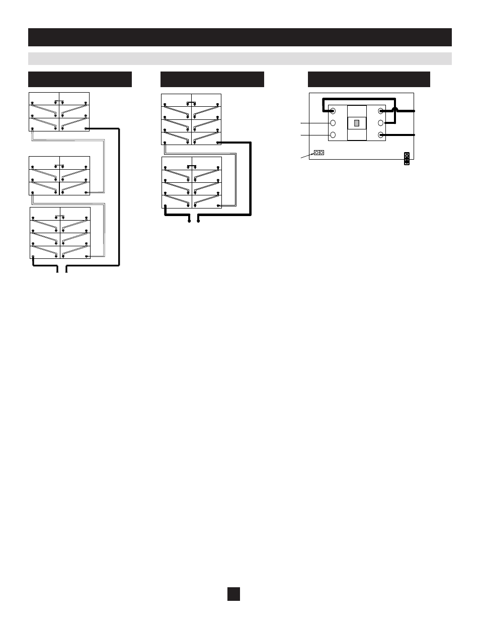
6.2 Battery and Breaker Diagrams
6. Diagrams
(continued)
Shelf #2
Shelf #2
Shelf #3
AC Input for
Battery Charger
To UPS Positive
To UPS Negative
Battery Positive
Battery Negative
UL Listed Breaker
Shelf #1 (Bottom)
Shelf #1 (Bottom)
To Fuse or Breaker Termination
To Fuse or Breaker Termination
Notes:
• All internal wiring is UL-listed, MTW, 125C Hi-Flex cable.
• Terminal block is UL-recognized and rated for 600 VDC.
• Breaker is UL-listed and rated for 100 A, 600 VDC, 25 KAIC.
• Cabinets with breakers are shipped with the breaker in the off/open position.
• Battery arrangements shown are typical but may vary depending on cabinet and battery type.
240 VDC Battery Diagram
192 VDC Battery Diagram
192/240 VDC Breaker Diagram
- Line Conditioner 230V (12 pages)
- Line Conditioner 230V (6 pages)
- TM500 (4 pages)
- BP480V140 (2 pages)
- OMNI1500XLNAFTA (5 pages)
- BP36V42-3U (2 pages)
- APSX750F (4 pages)
- Omnismart OMNIVS500 (2 pages)
- INTERNETX525 (1 page)
- HCRK-36 (3 pages)
- P004-002-5 (2 pages)
- BP240V120 (2 pages)
- Switched Rack PDU (10 pages)
- OMNIVSINT500 (24 pages)
- OmniPro 675 (20 pages)
- OMNISMART 1050M (1 page)
- BP48V212U (12 pages)
- BCPRO600 (1 page)
- ECO Series (2 pages)
- BP36VXR (3 pages)
- OMNI750ISO (5 pages)
- External Battery Pack BP240V557C-1PH (2 pages)
- 93-2007 (200106010) (22 pages)
- Omni VS UPS Systems OMNIVS800 (24 pages)
- 1500RMXL2UA (6 pages)
- BC350 (1 page)
- UPS System AVRX550U (2 pages)
- TE600 (1 page)
- BP192V18-4U (3 pages)
- HCRK-3 (12 pages)
- XL (36 pages)
- 93-2024 (7 pages)
- DCOW 2 (1 page)
- HT1500UPS (2 pages)
- 2U Tower Stand (1 page)
- P007-002 (2 pages)
- LS606M (2 pages)
- 120 (2 pages)
- HDMI ACTIVE EXTENDER B122-000 (2 pages)
- P047-006 (2 pages)
- BP48V242U (16 pages)
- UT3012UL (1 page)
- BP240V787C-1PH (2 pages)
- P005-010 (2 pages)
- B116-002 (4 pages)