Tyan Computer Transport GX21 B2735 User Manual
Tyan Computer Hardware
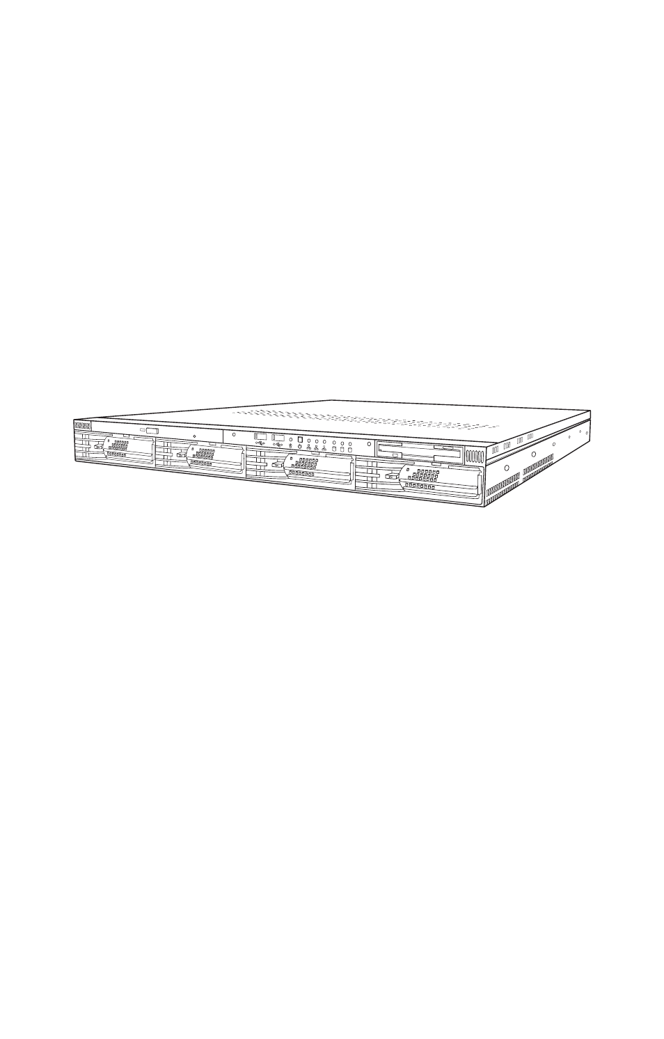
Table of contents
Document Outline
- Transport GX21
- B2735
- User’s Manual
- Preface
- Table of Contents
- Chapter 1: Overview
- Chapter 2: Setting up
- 2.1 Before you begin
- 2.2 Installing motherboard components
- 2.2.1 Removing the chassis cover
- 2.2.2 Installing CPUs
- 1. Remove the chassis cover as described in section 2.2.1 Removing the chassis cover.
- 2. Locate the CPU sockets on the motherboard as shown below.
- 3. Lift the CPU locking lever as shown below.
- 4. Place the CPU in the CPU socket, ensuring that pin 1 is located as shown in the following illustration.
- pin 1
- 2.2.3 Installing memory
- 1. Remove the chassis cover as described n section 2.2.1 Removing the chassis cover.
- 2. Locate the memory slots on the motherboard.
- 3. Press the memory slot locking levers in the direction of the arrows as shown below.
- 4. Align the memory module with the slot. The module will fit only one way in the slot. Ensure that indentations in the memory module line up with corresponding notches in the memory slot.
- 5. Insert the memory module into the slot as shown.
- 6. Ensure that the locking levers are firmly in place and that the memory module is properly seated in the slot.
- 2.2.4 Installing a PCI card
- 1. Remove the chassis cover as described in section 2.2.1 Removing the chassis cover.
- 2. Remove the PCI retention bar.
- 3. Remove the screw securing the PCI faceplate to the chassis.
- 4. Slide the PCI card clamp out as shown.
- 5. Slide the dust cover out.
- 6. Press the PCI card into place in the slot on the riser card. Ensure that the card is seated properly in the slot on the riser card and that the riser card is properly seated in its slot on the motherboard.
- 7. Reinsert the PCI card clamp.
- 8. Insert the screw to secure the PCI card to the chassis.
- 2.3 Installing a hard drive
- 2.3.1 Installing internal hard drives (B2735G21S2)
- 2.3.1.1 Installing an IDE hard drive
- 1. Remove the chassis cover as described in section 2.2.1 Removing the chassis cover.
- 2. If you are replacing an existing IDE hard drive, remove the power and data cables from it.
- 3. Remove the screw securing the HDD tray to the chassis.
- 4. Slide the HDD tray out of the chassis.
- 5. Place a new HDD in the tray and slide it to the front.
- 6. Secure the new disk drive in the tray with 4 screws.
- 7. Reinsert the HDD tray and secure it to the chassis with a screw.
- 8. Connect the IDE data cable and power cable to the HDD.
- 1. Remove the chassis cover as described in section 2.2.1 Removing the chassis cover.
- 2. If you are replacing an existing S-ATA hard drive, remove the power and data cables from it.
- 3. Remove the screw securing the HDD tray to the chassis.
- 4. Slide the HDD tray out of the chassis.
- 5. Place a new HDD in the tray and slide it to the front.
- 6. Secure the new disk drive in the tray with 4 screws.
- 7. Reinsert the HDD tray and secure it to the chassis with a screw.
- 8. Connect the S-ATA data cable and power cable to the HDD.
- 2.3.2 Installing an external S-ATA hard drive (B2735G21S4H)
- 1. Remove the chassis cover as described in section 2.2.1 Removing the chassis cover.
- 2. Press the drive bay locking latch in the direction of the arrow (1) and pull the locking lever open (2).
- 3. Slide the drive bay out.
- 4. Place a S-ATA drive in the drive bay.
- 5. Insert four screws to secure the new unit in the drive bay.
- 6. Reinsert the drive bay into the chassis. Ensure that the rear connector of the new drive is firmly seated in the backplane.
- 2.3.3 Installing an external SCSI hard drive (B2735G21U4H)
- 1. Remove the chassis cover as described in section 2.2.1 Removing the chassis cover.
- 2. Press the drive bay locking latch in the direction of the arrow (1) and pull the locking lever open (2).
- 3. Slide the drive bay out.
- 4. Insert a SCSI hard drive in the drive bay.
- 5. Insert four screws to secure the new unit in the drive bay.
- 6. Reinsert the drive bay into the chassis. Ensure that the rear connector of the new drive is firmly seated in the backplane.
- 2.3.1 Installing internal hard drives (B2735G21S2)
- 2.4 Rack mounting
- 1. Screw the mounting ears to the Transport GX21 as shown using 4 screws from the supplied nuts, screws and washers kit.
- 2. Screw the sliding rail mounting brackets to the sliding rails as shown, using the short black screws from the supplied nuts, screws and washers kit.
- 3. Fully extend the sliding rails until they lock.
- 4. Screw each sliding rail to the side of the Transport GX21 as shown. You will need 3 short, silver colored screws from the supplied nuts, screws and washers kit, for each rail.
- 5. Return the sliding rails to their shortest position.
- 6. With the rails in their shortest position, adjust both front mounting brackets so that they are flush with the front of the unit.
- 7. Accurately measure the depth of your rack and adjust the rear brackets accordingly.
- 8. When all brackets are positioned correctly, tighten them.
- 9. Lift the unit into place in the rack and screw it into place as shown.
- Chapter 3: Replacing pre-installed components
- 3.1 Introduction
- 3.2 Replacing motherboard components
- 3.3 Replacing the CD-ROM drive
- 3.3.1 Replacing the slim CD-ROM drive (B2735G21S2)
- 1. Remove the chassis cover as described in section 2.2.1 Removing the chassis cover.
- 2. Locate the drive bay housing the FDD and slim CD-ROM drive and remove power and data cables from both.
- 3. Remove the two screws that secure the CD-ROM backplane to the CD-ROM drive.
- 4. Remove the four screws that secure the drive bay to the chassis and lift the drive bay free.
- 5. Slide the slim CD-ROM from the drive bay.
- 3.3.2 Replacing the CD-ROM drive (B2735G21U4H/B2735G21S4H)
- 1. Remove the chassis cover as described in section 2.2.1 Removing the chassis cover.
- 2. Remove the power and data cables from the CD-ROM drive.
- 3. Remove the two screws that secure the CD-ROM bracket to the chassis and lift it free.
- 4. Lift the CD-ROM drive from the chassis.
- 5. Remove the two screws that secure the CD-ROM adapter to the CD-ROM drive and remove it.
- 3.3.1 Replacing the slim CD-ROM drive (B2735G21S2)
- 3.4 Replacing the floppy disk drive
- 3.4.1 Replacing the floppy disk drive (B2735G21S2)
- 1. Remove the chassis cover as described in section 2.2.1 Removing the chassis cover.
- 2. Locate the drive bay housing the slim CD-ROM drive and the FDD and remove power and data cables from both.
- 3. Remove the 4 screws that secure the drive bay to the chassis and lift the drive bay free.
- 4. Remove the four screws that secure the FDD in the drive bay and slide the unit out of the drive bay.
- 3.4.2 Replacing the floppy disk drive (B2735G21S4H/B2735G21U4H).
- 3.4.1 Replacing the floppy disk drive (B2735G21S2)
- 3.5 Replacing the LED control board
- 3.6 Replacing the storage backplane
- 3.6.1 S-ATA backplane (B2735G21S4H)
- 3.6.1.1 Replacing the S-ATA backplane (B2735G21S4H)
- 1. Remove the chassis cover as described in section 2.2.1 Removing the chassis cover.
- 2. Remove the two screws that secure the metal retaining plate to the chassis and lift it free as shown.
- 3. Remove all cables connected to the S-ATA backplane, including front panel cable, power cables, and S-ATA data cables.
- 4. Remove the six screws that secure the S-ATA backplane bracket to the chassis.
- 5. Remove the S-ATA backplane bracket and backplanes free from the chassis.
- J3 serial ATA 7 pin connector
- 3.6.2 SCSI backplane (B2735G21U4H)
- 3.6.2.1 Replacing the SCSI backplane (B2735G21U4H)
- 1. Remove the chassis cover as described in section 2.2.1 Removing the chassis cover.
- 2. Remove the two screws that secure the metal retaining plate to the chassis and lift it free as shown.
- 3. Remove all cables connected to the SCSI backplane, including power cables, SCSI cable, and floppy disk drive cable.
- 4. Remove the 10 screws that secure the SCSI backplane to the chassis and lift the backplane free.
- J5 80 pin SCA2
- 3.6.1 S-ATA backplane (B2735G21S4H)
- 3.7 Replacing the power supply
- 1. Remove the chassis cover as described in section 2.2.1 Removing the chassis cover.
- 2. Remove the four screws that secure the fan assembly to the chassis and lift it free.
- 3. Disconnect power cables from the motherboard, HDDs, FDDs, CD-ROM drive and fans. See section 3.4.2 Disconnecting Cables for details on how to do this.
- 4. Remove the four screws that secure the power supply to the chassis and lift the unit free.
- 3.8 Replacing the cooling fans
- 1. Remove the chassis cover as described in section 2.2.1 Removing the chassis cover.
- 2. Remove the PCI retention bar
- 3. Remove the power cables for the 5 fans from the motherboard.
- 4. Remove the four screws that secure the fan bracket to the chassis.
- 5. Lift the fan bracket free of the unit
- 6. Remove the four screws securing each fan to the fan bracket to remove them from the fan bracket.
- 3.8.1 Cooling fan connections
- BIOS setup utility
- Menu bar selections
- BIOS legend bar
- BIOS main menu
- BIOS advanced menu
- BIOS advanced menu
- CPU configuration submenu
- IDE configuration submenu
- IDE configuration submenu
- S-ATA Port/Primary IDE/Secondary IDE Configuration submenu
- Floppy configuration submenu
- Floppy configuration submenu
- Super I/O configuration submenu
- Super I/O configuration submenu
- ACPI settings submenu
- Advanced ACPI configuration submenu
- Advanced ACPI configuration
- DMI event logging submenu
- Remote access configuration
- USB configuration menu
- USB configuration submenu
- USB mass storage device configuration
- Hardware monitor submenu
- Hardware monitor submenu
- Advanced PCI/PnP Menu
- Advanced PCI/PnP Menu
- BIOS boot settings menu
- Boot settings configuration submenu
- Boot settings configuration submenu
- Boot device priority submenu
- Boot device priority submenu
- Hard disk drives submenu
- Removable drives submenu
- ATAPI CD-ROM drives submenu
- BIOS security menu
- BIOS security menu
- BIOS chipset settings
- Northbridge chipset configuration menu
- Southbridge chipset configuration menu
- Intel PCI-64 Hub 2 configuration submenu
- BIOS exit menu
- BIOS exit menu