TurboChef Technologies TurboChef User Manual
Page 56
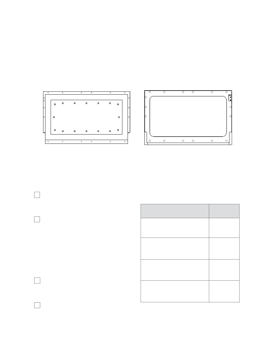
SHUNT CAVITY/PLATE
Tightening Sequence
SHUNT ASSY/DOOR COVER
Tightening Sequence
5
8
4
1
5
9
11
10
6
2
3
7
12
14
15
13
16
14
8
1
15
9
10
16
6
2
3
7
17
11
12
13
4
F I G U R E
36: Oven Door Assembly: Tightening Specs
Critical Adjustment Notes (Figure 35)
1. Orient with the gasket seam at the bottom of
the door assembly. Gasket should be straight
with no twists or pinching.
2. Attach insulation (Item 94) to the inside of the
door cover using aluminum tape (Item 98).
x
D O N O T
block openings at bottom.
3. Item 94 (insulation) not shown for clarity.
4. Door should be flat without twisting or
warpage after tightening all hardware.
5. Refer to the chart to the right for torque specs.
Refer to Figure 36, above, for tightening
sequences.
6. Attach Item 99 with adhesive backing using
the two locating holes on the front cover.
PART
TORQUE
VALUE
90. Bolt, 1/4”-20 x 1.00
80 In-Lbs
(9.04 Nm)
85. Nut, Keps #8-32
(Assembled by factory)
21 In-Lbs
(2.37 Nm)
96. Screw, 8-32 x 3/8”
Torx Security
21 In-Lbs
(2.37 Nm)
97. Screw, 8 x 1/2” PTH
21 In-Lbs
(2.37 Nm)
SCREW TORQUE CHART
Refer to Figures 35, 36.
THE OVEN DOOR
45