Microwave circuit – TurboChef Technologies C3/CMulti User Manual
Page 88
Microwave Circuit
9-6
Magnetron High Voltage Transformer (102093)
The magnetron transformer is a ferro-resonant
design which limits fault currents and minimizes
magnetron power changes due to input voltage
changes.
An
automatic
resetting
over-
temperature switch is embedded in the high
voltage secondary winding and removes power
form the primary winding if an over-temperature
condition occurs.
In the C3 SERIES a separate transformer is used
to preheat the filament for the magnetron for
better
operation.
+(B)
0
-(C)
HV TRANSFORMER
OUTPUT VOLTAGE
MAGNETRON VOLTAGE
Current
Flow
2400
+
-
+
-
2400
VDC
Current
Flow
+
-
-
+
2400
2400
VDC
4800
VDC
+(B)
(A)
-
(C)
- 4800 V
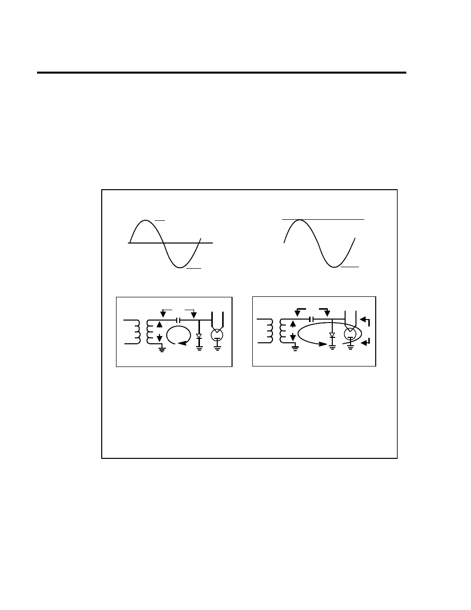
CAPACITOR CHARGES ON
POSITIVE VOLTAGE SWING
CHARGED CAPACITOR PLUS TRANSFORMER
ON NEGATIVE VOLTAGE SWING
+2400 V
-2400 V
(A)
0
1. The Magnetron Transformer steps up the input voltage to approximately 2400 volts peak
(4800 volts peak to peak).
2. The High Voltage Capacitor charges to 2400 volts on the positive going voltage via the
High Voltage Diode’s forward conduction.
3. The Magnetron Transformer plus the charged High Voltage supply up to - 4800 volts to the
Magnetron on the negative going voltage (High Voltage Diode is back biased).
4. The Magnetron converts the negative input voltage (and Current) to RF energy at 2450
MHz with approximately 60% efficiency.
WARNING: DO NOT ATTEMPT TO MEASURE THESE VOLTAGES
FIGURE 9 - 2 Magnetron High Voltage Power Supply