3x-5x series standard control panel rear view, 3 500-3x-5x series control panel connections – Trilogy Touch Technology Trilogy Commander Digital Intercom 9 User Manual
Page 39
Commander Installation Guide
Issue 9
Trilogy Communications Limited
Page 39 of 81
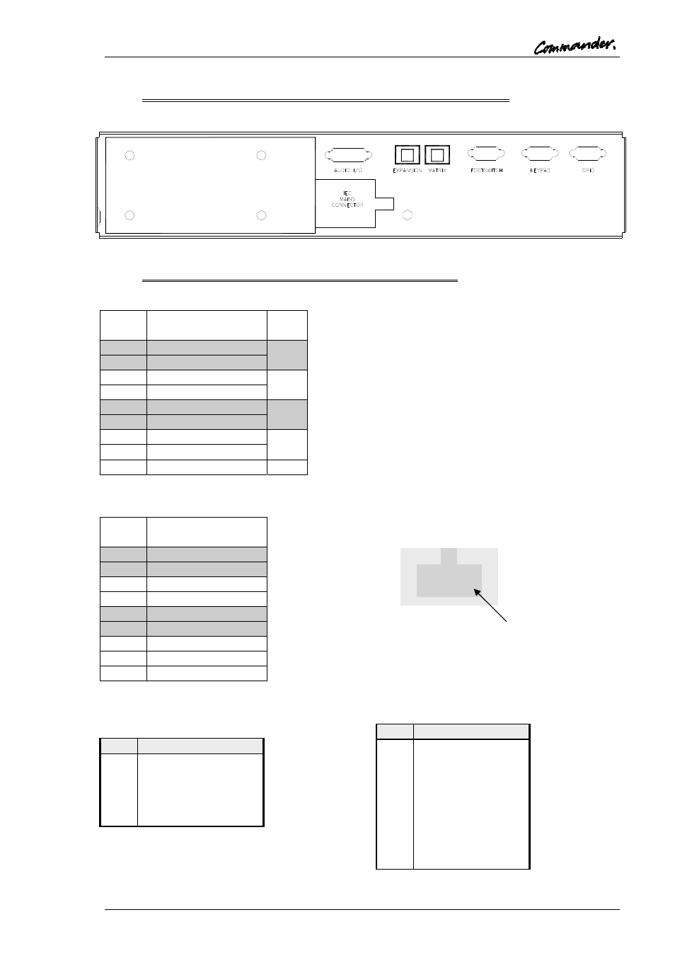
5.5.2 500-3X-5X SERIES STANDARD CONTROL PANEL REAR VIEW
5.5.3 500-3X-5X SERIES CONTROL PANEL CONNECTIONS
Matrix – RJ-45 fixed socket on panel
RJ-45
Pin
Function
1
Panel Data out +
Pair
1
2
Panel Data out -
3
Panel Data In +
Pair
2
6
Panel Data In -
5
Panel Audio out +
Pair
3
4
Panel Audio out -
7
Panel Audio in +
Pair
4
8
Panel Audio in -
Cable
Screen
Expansion Port – RJ45 socket
RJ-45
Pin
Function
1
Panel Data in +
2
Panel Data in -
3
Panel Data out +
6
Panel Data out -
5
Panel Audio out +
4
Panel Audio out -
7
Panel Audio in +
8
Panel Audio in -
Cable
Screen
Headset - 5 Pin XLR Fixed Socket (front
panel)
Pin
Function
1
Mic IN (Screen)
2 Mic
IN
3
Headset Gnd
4 Headset
Out
5 Headset
Out
Foot Switch - D9 Fixed Socket
Pin
Function
1
Foot Switch Input
2 No
Connection
3 Chassis
Ground
4 No
Connection
5 No
Connection
6 Ground
7 No
Connection
8 No
Connection
9 No
Connection
Matrix and Expansion RJ45
socket (view from rear of panel)
PIN 1