Overview – Tripp Lite B064-016 User Manual
Page 3
1
1
5
6
7
2
3
4
2
3
5
6
7
4
3
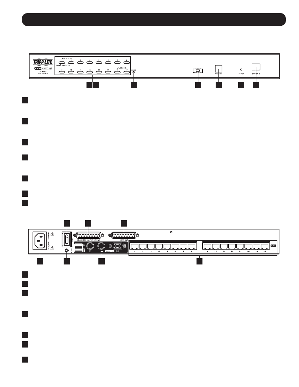
Overview
Component Features
Front Panel
1
Push-Buttons: Press a push-button to bring the KVM focus to that port. Simultaneously pressing push-buttons 1 and
2 for three seconds will perform a keyboard/mouse reset. Simultaneously pressing push-buttons 15 and 16 for three
seconds will invoke Auto Scan Mode. (See F7:SCAN on page 18 for details.)
2
Port LEDs: Each push-button contains two LEDs; an Online LED on the left, and a Selected LED on the right. When a
computer is connected to a port and powered-ON, that port’s Online LED illuminates green. When a port has the focus of
the KVM, it’s Selected LED illuminates orange. When accessed in Auto Scan Mode, the port’s Selected LED flashes.
3
Reset Button: Pressing the reset button performs a system reset, which is the same as turning the KVM switch OFF and
then back ON. Note: This button is semi-recessed and will need to be pressed with a small object, such as a paperclip.
4
Firmware Upgrade Switch: In normal KVM operation, this switch should always be set to the Normal position. In the
event of an unsuccessful firmware upgrade, this switch will need to be set to the Recover position in order to perform a
firmware upgrade recovery. (See Firmware Upgrade Recovery on page 20 for details.)
5
Firmware Upgrade Port: The included firmware upgrade cable connects to the KVM switch here during a firmware
upgrade.
6
Power LED: This LED illuminates blue when the KVM switch is connected to a power source and turned on.
7
Station ID LED: This numerical LED displays the KVM switches position in a daisy-chain installation, from 01 to 32.
Rear Panel
1
Power Input (C14): The included C13 to 5-15P power cord connects to the KVM switch here.
2
Power Switch: Turn the KVM switch ON/OFF using this switch.
3
Daisy-Chain In Port: When daisy-chaining KVM switches together, this DB25 Female port connects to the Daisy-Chain
Out port of the previous KVM switch in the installation using a Tripp Lite P772-Series Daisy-Chain Cable. (See Daisy-Chain
Installation on page 7 for details.)
4
Daisy-Chain Out Port: When daisy-chaining KVM switches together, this DB25 Male port connects to the Daisy-Chain In
port of the next KVM in the installation using a Tripp Lite P772-Series Daisy-Chain Cable. (See Daisy-Chain Installation on
page 7 for details.)
5
Grounding Terminal: The included grounding wire connects the KVM switch here.
6
Console Ports: The keyboard, monitor and mouse connect to the KVM switch here. The console ports include a VGA
(HD15) monitor port, two PS/2 keyboard/mouse ports and two USB keyboard/mouse ports.
7
Computer Ports: The Cat5e/6 cables that connect to each computer’s Server Interface Unit (SIU) plug into to the KVM
here.