Adjustment mode setting flow chart, P. 68) – TOA Electronics A-9060S User Manual
Page 68
68
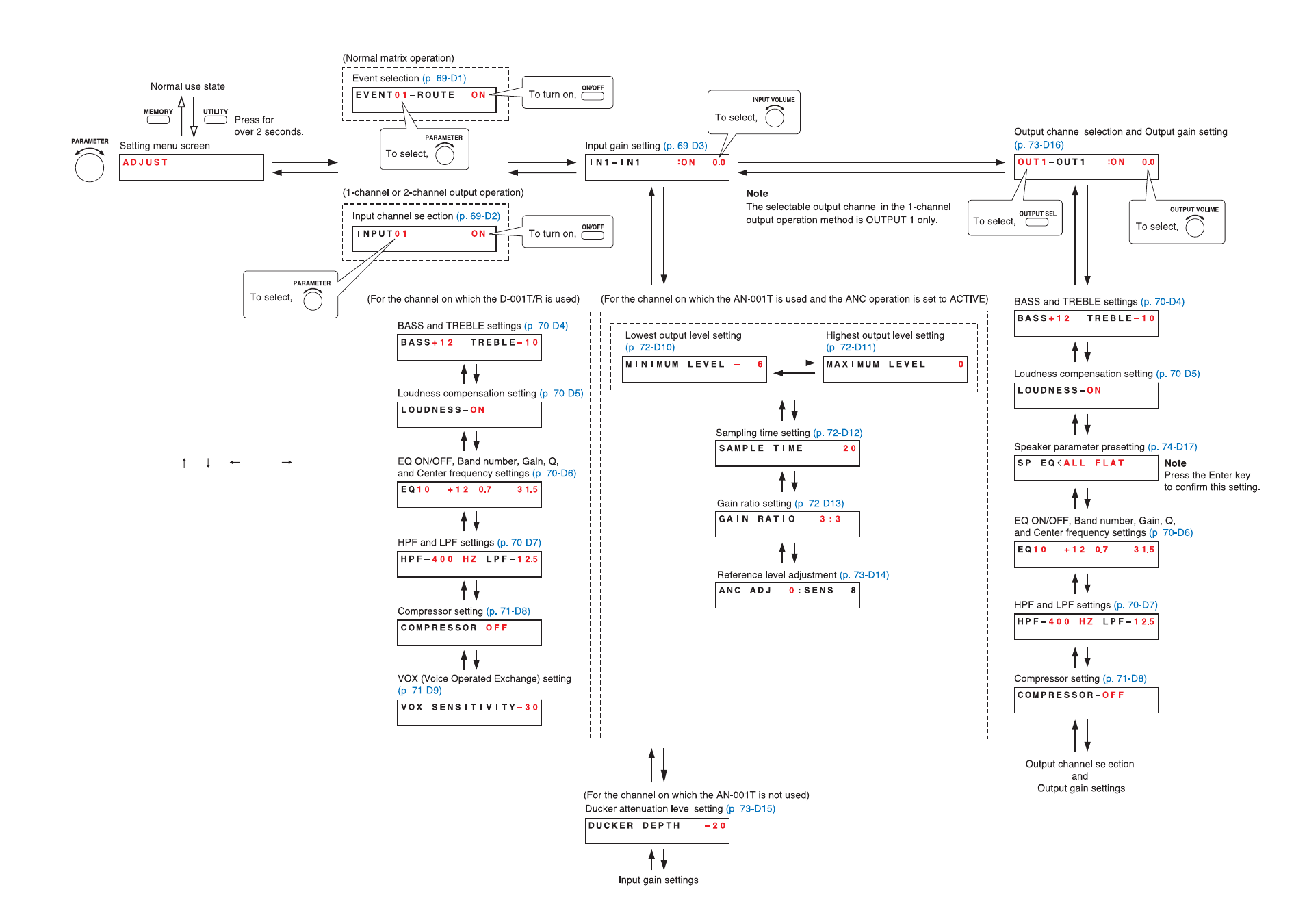
13.8.2. Adjustment mode setting flow chart
The screen display examples shown at right may differ
from actual displays.
The on-screen indications shown in red here (actually
shown by flashing cursors) are parameters or setting
contents to be selected with the Parameter setting knob,
input channel selection key or other designated keys.
The indications of the [ ], [ ], [
], and [
] arrows
represent that the screen is switched with the Screen
shift key.
Unless otherwise specified, use the Parameter setting
knob for each parameter selection.