3 configuring the multiple stp, 1 defining mstp properties – TP-Link TL-SG3109 User Manual
Page 69
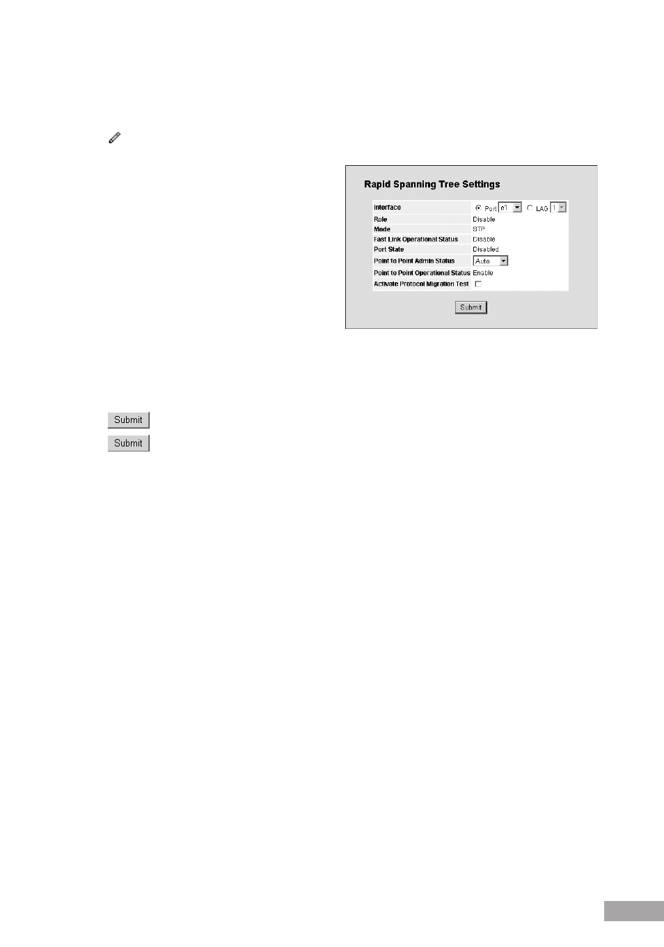
Point-to-Point Operational Status — Displays the point-to-point operating state.
LAG — Displays the LAG to which the interface is attached.
2. Click
. The RSTP Settings Page opens:
Figure 88: RSTP Settings Page
The RSTP Settings Page contains the following fields in
addition to the settings listed in the RSTP Page:
Activate Protocol Migration — Indicates whether
sending Link Control Protocol (LCP) packets to
configure and test the data link is enabled. The possible
field values are:
– Checked — Enables the Protocol Migration.
– Unchecked — Disables the Protocol Migration.
3. In the RSTP Settings Page, modify the following fields as required: Point-to-Point Admin Status, Point-to-Point
Operational Status.
4. Check the "Activate Protocol Migration Test" check box to activate Protocol Migration.
5. Click
.
6. Click
in the RSTP Page. The RSTP parameters are saved, and the device is updated.
9.3 Configuring the Multiple STP
Multiple Spanning Tree Protocol (MSTP) provides differing load balancing scenarios. For example, while port A is blocked in
one STP instance, the same port can be placed in the Forwarding state in another STP instance.
This section contains the following topics:
Defining MSTP Properties
Configuring MSTP Instances
Configuring MSTP VLAN Instances
Configuring MSTP Interface Settings
9.3.1 Defining MSTP Properties
The MSTP Properties Page contains information for defining global MSTP settings, including region names, MSTP revisions,
and maximum hops.
To define MSTP:
1. Click
System > Bridging Config > Spanning Tree > MSTP > Properties. The MSTP Properties Page opens: