Format characteristics, Electrical characteristics, Operating characteristics – Texas Instruments TPA3200D1 User Manual
Page 4
www.ti.com
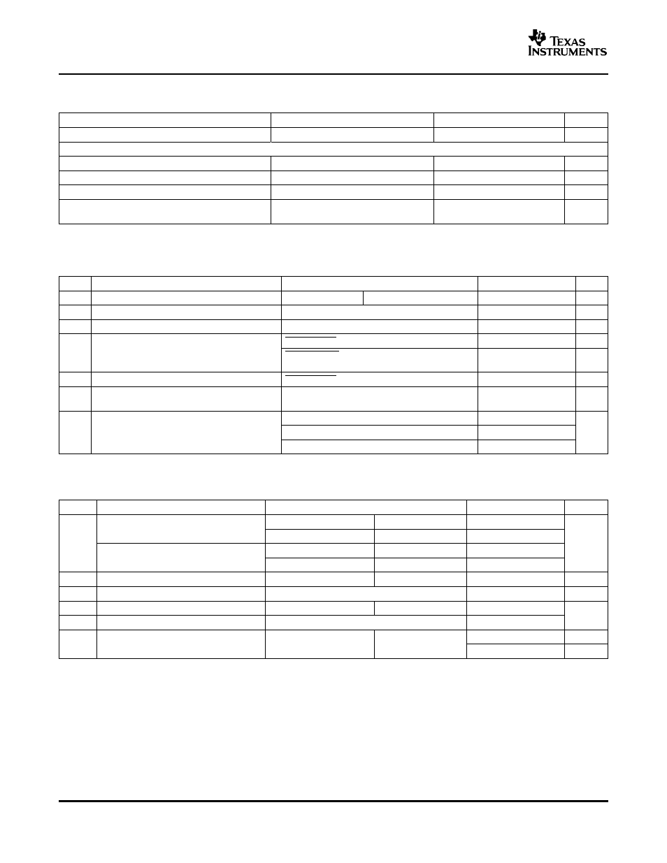
FORMAT CHARACTERISTICS
ELECTRICAL CHARACTERISTICS
OPERATING CHARACTERISTICS
TPA3200D1
SLOS442A – MAY 2005 – REVISED JULY 2005
All specifications at T
A
= 25
°
C, V
DD
= 5 V, f
S
= 44.1 kHz, system clock = 384 f
S
and 24-bit data, unless otherwise noted
PARAMETER
TEST CONDITIONS
MIN
TYP
MAX
UNIT
Resolution
24
Bits
Data
Audio-data interface format Audio
I
2
S, standard
Audio-data bit length Audio
16–24-bit (I
2
S), 16-bit (Right-justified)
Audio data format
MSB first, 2s complement
System clock frequency
128 f
S,
192 f
S
, 256 f
S
, 384 f
S
,
512 f
S
, 768 f
S
, 1152 f
S
at T
A
= 25
°
C, PV
CC
= V
CC
= 12 V (unless otherwise noted)
PARAMETER
TEST CONDITIONS
MIN
TYP
MAX
UNIT
|V
OS
|
Output offset voltage (measured differentially)
MUTE = 2 V
A
V
= 12 dB
100
mV
PSRR
Power supply rejection ratio
PV
CC
= 11.5 V to 12.5 V
–73
dB
V
REF
5 V regulator voltage
I
L
= 10 mA, V
CC
= 8 V – 18 V
4.55
4.9
5.45
V
SHUTDOWN = 2.0 V, No load
8
15
mA
I
CC
Supply current
SHUTDOWN = V
CC
, V
CC
= 18 V, PO = 20 W,
1.3
A
R
L
= 8
Ω
I
CC(SD)
Supply current shutdown mode
SHUTDOWN = 0.8 V
1
2
µA
Output transistor on resistance (high side and
r
DS(on)
I
O
= 0.5 A, T
J
= 25
°
C
0.5
0.6
0.7
Ω
low side)
GAIN1 = 0.8 V, GAIN0 = 0.8 V
10.9
12
13.1
G
Gain
GAIN1 = 0.8 V, GAIN0 = 2 V
17.1
18
18.6
dB
GAIN1 = 2 V, GAIN0 = 0.8 V
22.9
23.6
24.4
PV
CC
= V
CC
= 12 V, T
A
= 25
°
C unless otherwise noted
PARAMETER
TEST CONDITIONS
MIN
TYP
MAX
UNIT
Continuous output power at 10% THD+N
f = 1 kHz,
R
L
= 4
Ω
12.8
f = 1 kHz,
R
L
= 8
Ω
9
P
O
W
Continuous output power at 1% THD+N
f = 1 kHz,
R
L
= 4
Ω
10.3
f = 1 kHz,
R
L
= 8
Ω
7.5
THD+N
Total harmonic distortion plus noise
P
O
= 10 W, R
L
= 4
Ω
f = 20 Hz to 20 kHz
0.2%
B
OM
Maximum output power bandwidth
THD = 1%
20
kHz
k
SVR
Supply ripple rejection ratio
f = 1 kHz,
C
(BYPASS)
= 1 µF
–60
dB
SNR
Signal-to-noise ratio
P
O
= 10 W, R
L
= 4
Ω
95
C
(BYPASS)
= 1 µF,
f = 20 Hz to 22 kHz,
150
µV(rms)
V
n
Noise output voltage
A-weighted filter
Gain = 12 dB
–76.5
dBV
4