Zero flag, 2) i, S data format; l-channel = low, r-channel = high – Texas Instruments TPA3200D1 User Manual
Page 15: 1) 16-bit-word right justified
www.ti.com
LRCK
(2) I
2
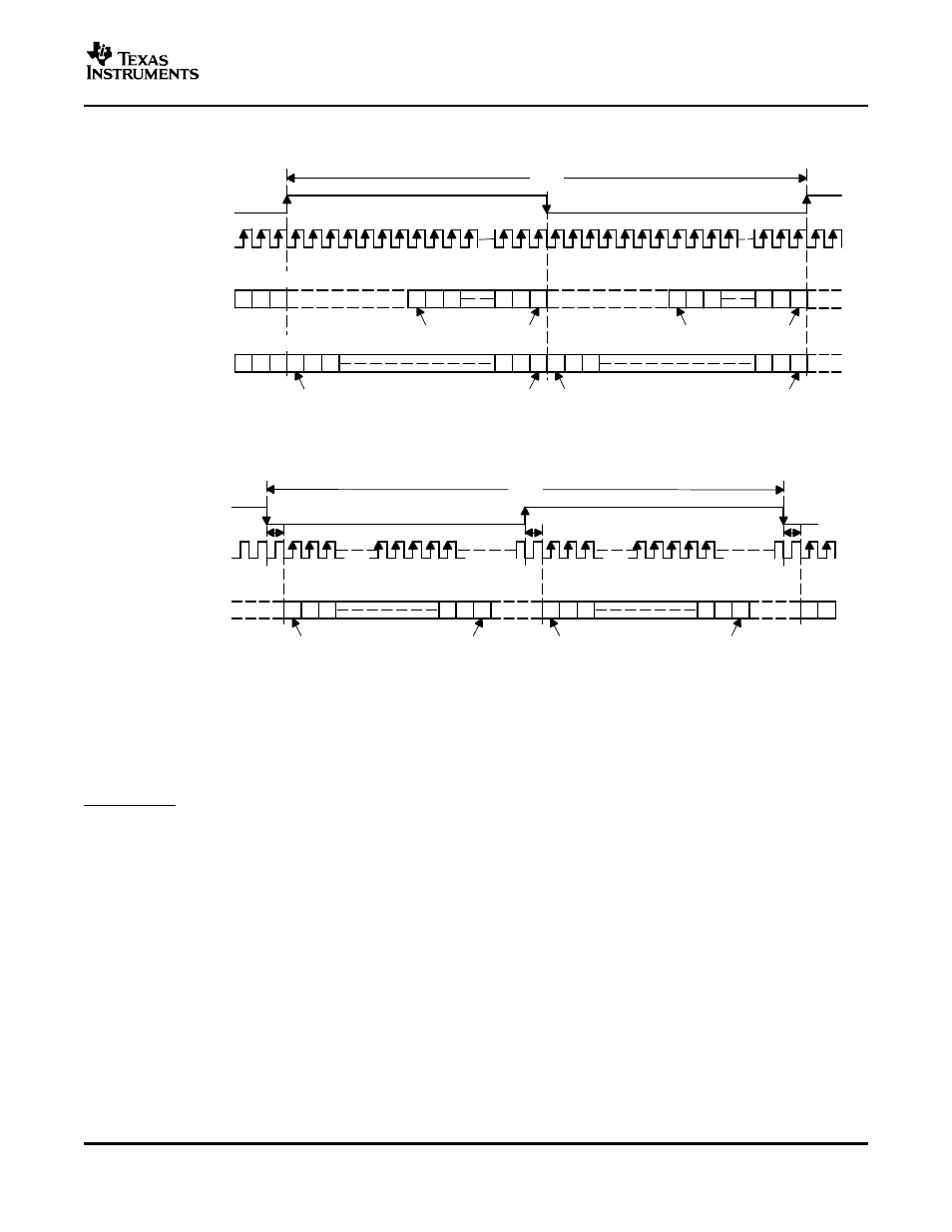
S Data Format; L-Channel = LOW, R-Channel = HIGH
1/f
S
(= 32 f
S
, 48 f
S,
or 64 f
S
)
(1) 16-Bit-Word Right Justified
1/f
S
(= 48 f
S
or 64 f
S
)
MSB
LSB
16-Bit Right-Justified, BCK = 32 f
S
16-Bit Right-Justified, BCK = 48 f
S
or 64 f
S
MSB
LSB
L-Channel
R-Channel
BCK
DATA
14 15 16
1
2
3
14 15 16
14 15 16
1
2
3
14 15 16
DATA
MSB
LSB
MSB
LSB
1
2
3
14 15 16
1
2
3
14 15 16
L-Channel
R-Channel
LRCK
BCK
DATA
1
2
3
1
2
MSB
N–2
N
N–1
LSB
1
2
3
MSB
N–2
N
N–1
LSB
ZERO FLAG
TPA3200D1
SLOS442A – MAY 2005 – REVISED JULY 2005
Figure 20. Audio Data Input Formats
ZERO (pin 39) is the L-channel and R-channel common zero flag pin. If the data for L-channel and R-channel
remains at a 0 level for 1024 sampling periods (or LRCK clock periods), the ZERO flag output is set to a logic 1
state.
The ZERO-pin output can be inverted using a standard logic gate or transistor, and connected to the
SHUTDOWN terminal (pin 13). This places the TPA3200D1 into a low-current state, conserving power, and
disables the switching outputs.
15