Driving the output into clipping, Output filter considerations – Texas Instruments TPA3200D1 User Manual
Page 19
www.ti.com
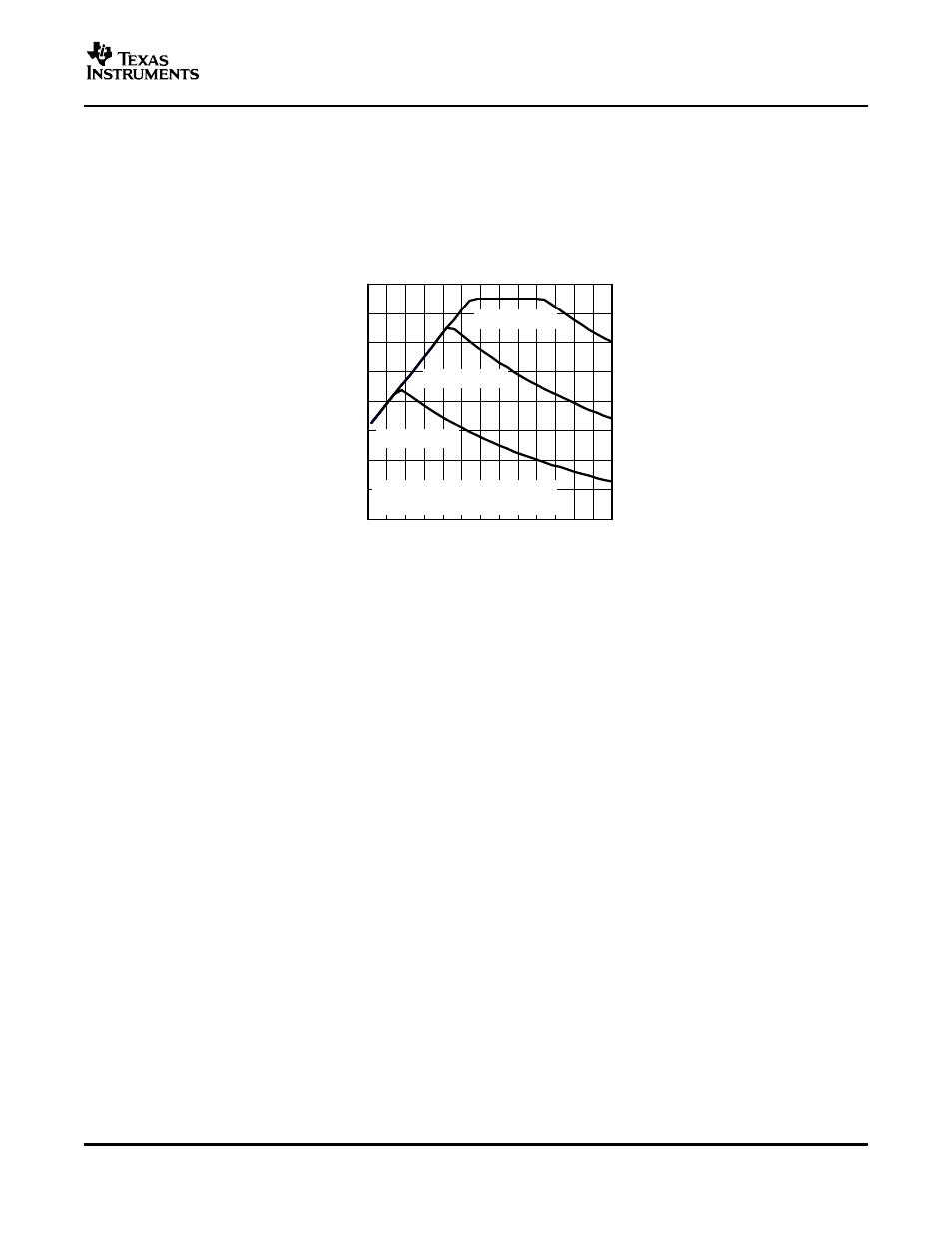
Maximum Allowable Output Power (Safe Operating Area)
5
7
9
11
13
15
17
19
21
3.6 4
5
6
7
8
9
10
V
CC
= 18 V
V
CC
= 15 V
V
CC
= 12 V
T
A
= 25
°
C,
10% THD Maximum
Z
L
− Load Impedance −
Ω
− Output Power − W
MAXIMUM OUTPUT POWER
vs
LOAD IMPEDANCE
P
O
Driving The Output Into Clipping
P
O(10% THD)
+
P
O(1% THD)
1.25
(1)
Output Filter Considerations
TPA3200D1
SLOS442A – MAY 2005 – REVISED JULY 2005
The TPA3200D1 can drive load impedances as low as 3.6
Ω
from power supply voltages ranging from 8 V to 18
V. To prevent device failure, however, the output power of the TPA3200D1 must be limited.
shows the
maximum allowable output power versus load impedance for three power supply voltages at an ambient
temperature of 25°C.
Figure 23. Output Power
The output of the TPA3200D1 may be driven into clipping to attain a higher output power than is possible with no
distortion. Clipping is typically quantified by a THD measurement of 10%. The amount of additional power into
the load may be calculated with
Equation 1
.
For example, consider an application in which the TPA3200D1 drives an 8-
Ω
speaker from an 18-V power
supply. The maximum output power with no distortion (less than 1% THD) is 16 W, which corresponds to a
maximum peak output voltage of 16 V. For the same output voltage level driven into clipping (10% THD), the
output power is increased to 20 W.
A ferrite bead filter (shown in
) should be used in order to pass FCC and/or CE radiated emissions
specifications and if a frequency sensitive circuit operating higher than 1 MHz is nearby. The ferrite filter reduces
EMI around 1 MHz and higher (FCC and CE only test radiated emissions greater than 30 MHz). When selecting
a ferrite bead, choose one with high impedance at high frequencies, but very low impedance at low frequencies.
Use an additional LC output filter if there are low frequency (<1 MHz) EMI sensitive circuits and/or there are long
wires (greater than 11 inches) from the amplifier to the speaker, as shown in
and
19