Application information, Figure 17. typical application circuit – Texas Instruments TPA3200D1 User Manual
Page 12
www.ti.com
APPLICATION INFORMATION
1 mF
1 mF
220 pF
VCC
PGND and DGND
connected at
power supply
Shutdown Control
{
VDD
GAIN0
VCOM
GAIN1
VCC
120 kW
NC
DGND
VDD
LRCK
DGND
BCK
DATA
LR_SEL
VDD
SHUTDOWN
PGND
PGND
VCLAMP
BSN
OUTN
OUTN
PGND
PVCC
NC
0.1 mF
1 mF
51 W
0.22 mF
OUTN
Ferrite
Bead
1 nF
OUTP
Ferrite
Bead
Ferrite
Bead
1 nF
0.22 mF
22 mF
FORMAT
SCLK
COSC
PGND
AGND
BSP
OUTP
OUTP
ROSC
PVCC
AGND
MUTE
DGND
DEMP
DGND
FLT1
ZERO
FLT2
VCC
VREF
BYPASS
PGND
10 mF
10 F
m
22 nF
Gain Control
{
I
2
S/RJ Clocks
& Data
51 W
}
Control
Inputs
Zero Flag Output
PGND
DGND
1 mF
1 mF
TPA3200D1
SLOS442A – MAY 2005 – REVISED JULY 2005
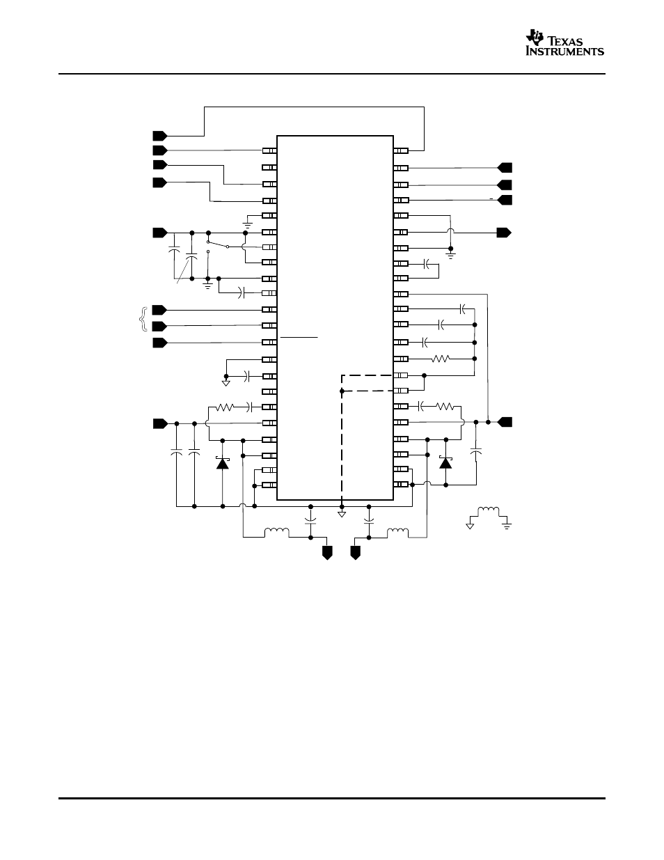
Figure 17. Typical Application Circuit
12
See also other documents in the category Texas Instruments Receivers and Amplifiers:
- THS4151 (26 pages)
- TRF1500 (74 pages)
- SLOU082 (28 pages)
- TAS5508-5121K8EVM (24 pages)
- TPA6102A2 (16 pages)
- TPA3001D1EVM (22 pages)
- TPA6030A4 (25 pages)
- TPA701 (26 pages)
- TPA6110A2 MSOP (18 pages)
- TAS5727 (21 pages)
- THS4503EVM (28 pages)
- TPA005D02 (50 pages)
- SLOU121 (42 pages)
- TPA0243 (20 pages)
- TPA0253 (20 pages)
- TPA102 MSOP (26 pages)
- THS4131 (26 pages)
- SLOU020A (28 pages)
- TPA751 MSOP (20 pages)
- TPA005D12 (44 pages)
- TPA6139A2 EVM (8 pages)
- TPA0103 (32 pages)
- SLOU106 (26 pages)
- THS4141 (26 pages)
- THS3001 (20 pages)
- TPA0233 (20 pages)
- TPA2008D2 (26 pages)
- 2004 (20 pages)
- TPA3003D2 (36 pages)
- SLAU081 (44 pages)
- TPA301 (28 pages)
- TPA3100D2 (11 pages)
- SLOU023A (26 pages)
- TAS5110D6REF (45 pages)
- TA5704EVM (27 pages)
- TAS5518 (20 pages)
- APA100 (42 pages)
- TAS5066PAG (22 pages)
- TPA6204A1 (16 pages)
- THS4150 (26 pages)
- TPA311 (28 pages)
- TPA3008D2 (31 pages)
- TPA6101A2 (16 pages)