Tpa3200d1 modulation scheme – Texas Instruments TPA3200D1 User Manual
Page 18
www.ti.com
TPA3200D1 Modulation Scheme
0 V
−12 V
+12 V
Current
OUTP
OUTN
Differential
Voltage
Across
Load
0 V
−12 V
+12 V
Current
OUTP
OUTN
Differential
Voltage
Across
Load
Output = 0 V
Output > 0 V
TPA3200D1
SLOS442A – MAY 2005 – REVISED JULY 2005
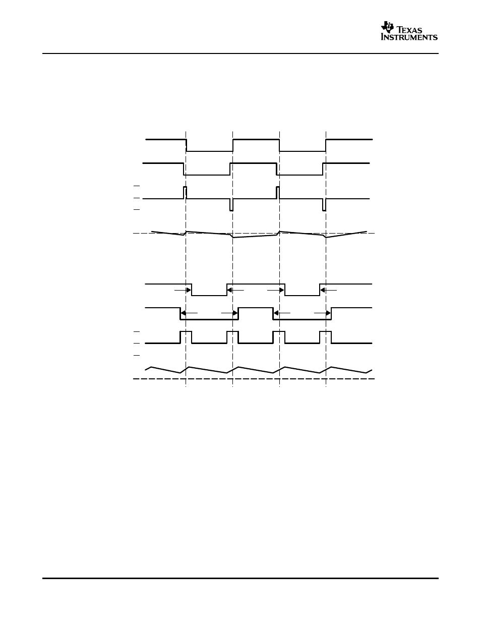
The TPA3200D1 uses a modulation scheme that still has each output switching from ground to V
CC
. However,
OUTP and OUTN are now in phase with each other with no input. The duty cycle of OUTP is greater than 50%
and OUTN is less than 50% for positive output voltages. The duty cycle of OUTP is less than 50% and OUTN is
greater than 50% for negative output voltages. The voltage across the load is 0 V throughout most of the
switching period, greatly reducing the switching current, which reduces any I
2
R losses in the load. (See
.)
Figure 22. The TPA3200D1 Output Voltage and Current Waveforms Into an Inductive Load
18
- THS4151 (26 pages)
- TRF1500 (74 pages)
- SLOU082 (28 pages)
- TAS5508-5121K8EVM (24 pages)
- TPA6102A2 (16 pages)
- TPA3001D1EVM (22 pages)
- TPA6030A4 (25 pages)
- TPA701 (26 pages)
- TPA6110A2 MSOP (18 pages)
- TAS5727 (21 pages)
- THS4503EVM (28 pages)
- TPA005D02 (50 pages)
- SLOU121 (42 pages)
- TPA0243 (20 pages)
- TPA0253 (20 pages)
- TPA102 MSOP (26 pages)
- THS4131 (26 pages)
- SLOU020A (28 pages)
- TPA751 MSOP (20 pages)
- TPA005D12 (44 pages)
- TPA6139A2 EVM (8 pages)
- TPA0103 (32 pages)
- SLOU106 (26 pages)
- THS4141 (26 pages)
- THS3001 (20 pages)
- TPA0233 (20 pages)
- TPA2008D2 (26 pages)
- 2004 (20 pages)
- TPA3003D2 (36 pages)
- SLAU081 (44 pages)
- TPA301 (28 pages)
- TPA3100D2 (11 pages)
- SLOU023A (26 pages)
- TAS5110D6REF (45 pages)
- TA5704EVM (27 pages)
- TAS5518 (20 pages)
- APA100 (42 pages)
- TAS5066PAG (22 pages)
- TPA6204A1 (16 pages)
- THS4150 (26 pages)
- TPA311 (28 pages)
- TPA3008D2 (31 pages)
- TPA6101A2 (16 pages)