Absolute maximum ratings, Dissipation ratings, Absolute maximum ratings dissipation ratings – Texas Instruments TPA3200D1 User Manual
Page 2
www.ti.com
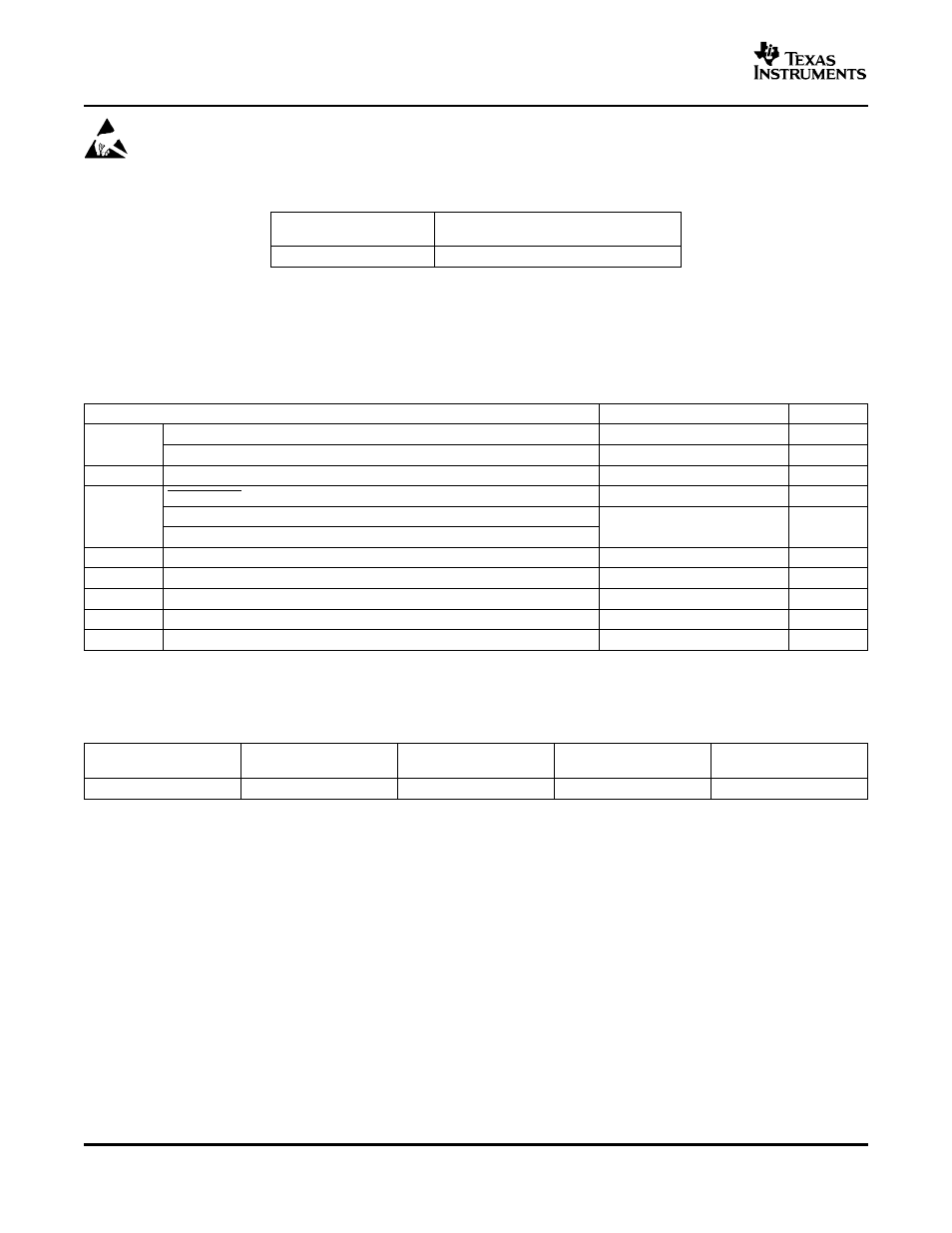
ABSOLUTE MAXIMUM RATINGS
DISSIPATION RATINGS
TPA3200D1
SLOS442A – MAY 2005 – REVISED JULY 2005
These devices have limited built-in ESD protection. The leads should be shorted together or the device
placed in conductive foam during storage or handling to prevent electrostatic damage to the MOS gates.
AVAILABLE OPTIONS
PACKAGED DEVICE
T
A
44-PIN (DCP)
(1)
–40
°
C to 85
°
C
TPA3200D1DCP
(1)
The DCP package is available taped and reeled. To order a taped
and reeled part, add the suffix R to the part number (e.g.,
TPA3200D1DCPR).
over operating free-air temperature range (unless otherwise noted)
(1)
TPA3200D1
UNIT
Supply voltage, VCC, PVCC
–0.3 to 21
V
V
SS
Supply voltage, VDD
–0.3 to 6.5
V
R
L
Load Impedance
≥
3.6
Ω
SHUTDOWN
– 0.3 to V
CC
+ 0.3
V
Vi
GAIN0, GAIN1, BCK, SCLK, DATA, LRCK, LR_SEL
–0.3 to V
DD
+ 0.3
V
FORMAT, MUTE, DEMP
Continuous total power dissipation
See Dissipation Rating Table
T
A
Operating free-air temperature range
–25 to 85
°
C
T
J
Operating junction temperature range
–25 to 150
°
C
T
stg
Storage temperature range
–65 to 150
°
C
Lead temperature 1.6 mm (1/16 inch) from case for 10 seconds
260
°
C
(1)
Stresses beyond those listed under absolute maximum ratings may cause permanent damage to the device. These are stress ratings
only, and functional operations of the device at these or any other conditions beyond those indicated under recommended operating
conditions is not implied. Exposure to absolute-maximum-rated conditions for extended periods may affect device reliability.
PACKAGE
T
A
≤
25
°
C
DERATING FACTOR
T
A
= 70
°
C
T
A
= 85
°
C
(1/
θ
JA
)
44-pin DCP
4.89 W
39.1 mW/
°
C
(1)
3.13 W
2.54 W
(1)
Based on a JEDEC high-K PCB with the PowerPAD™ soldered to a thermal land on the printed-circuit board. See the PowerPAD
Thermally Enhanced Package technical brief, literature number
SLMA0002.
The PowerPAD must be soldered to the PCB.
2