Wiring – Toshiba Uninterruptible Power System G8000 Series User Manual
Page 28
27
11. Wiring
11.1 Overview
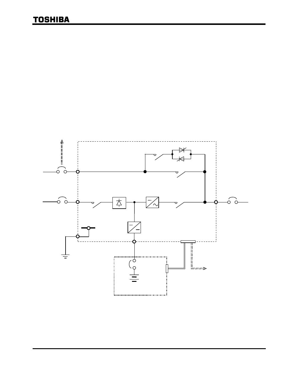
Figure 11.1 shows the external wiring diagram of G8000 UPS. Wiring work is summarized below.
1) Power cable connection for AC input, Bypass Input, AC output, and DC input at terminal blocks or
buses.
2) External breaker provision at AC input, Bypass Input, AC output, and DC input.
3) Earth ground wire at grounding electrode.
4) Control wire terminal TB1 (Battery cabinet and Bypass Breaker).
See corresponding section to each wiring term.
Figure 11.1 - External Wiring Diagram.
Battery
Breaker
< Battery Cabinet >
Bypass
Breaker
Bypass
3
φ
4W
Input
Breaker
AC Input
3
φ
3W
Output
Breaker
Output
3
φ
4W
DC input
Bypass
Contactor
Contactor + Thyristor
Input
Contactor
Inverter
Contactor
Inverter
Chopper
Charger
Rectifier
< UPS >
TB1
Ground
Wire
To Bypass
Breaker
To TB1
See also other documents in the category Toshiba Tools:
- Power Inverter (15 pages)
- 1800 (6 pages)
- TOSVERT VF-S11 (68 pages)
- Uninterruptible Power System G9000 (104 pages)
- Density (Consistency) Meter LQ500 (9 pages)
- MBSB80-225-43 (1 page)
- TOSNIC-7000S (53 pages)
- 1600EP Series (3 pages)
- 1500 (32 pages)
- TOSVERT VF-FS1 Series (16 pages)
- 4200FA XT1 (1 page)
- G3 Plus Pack (4 pages)
- Tosvert VF-A5 (149 pages)
- 1600 Series (3 pages)
- G9000 (100 pages)
- TEC EO1-33030 (54 pages)
- 1000 Series (2 pages)
- 1500 Plus (31 pages)
- G8000MM (6 pages)
- VT130G1 (99 pages)
- 4200FA Series (2 pages)
- VF-PS1 (10 pages)
- GX7 Series (6 pages)
- 4200FA XT (1 page)
- RMTI-EMD-HT (2 pages)
- W7 Series (6 pages)
- HX7 (6 pages)
- PDP002Z (18 pages)
- RELIABILITY IN MOTION 1700 (39 pages)
- 1700 Series (2 pages)
- G3 TOSVERT-130 (62 pages)
- B-852-TS12-QP (55 pages)
- 1000 (4 pages)
- E3 (7 pages)
- Adjustable Speed Drive H3 (122 pages)
- 55611-001 (2 pages)
- Black Gold Series (2 pages)
- Dura-Bull TX (6 pages)
- Current Relay RC803A-HP1 (19 pages)
- 1800 SERIES (2 pages)
- Isolated-Redundant UPS System (2 pages)
- Tosvert VF-AS1 (312 pages)
- RELIABILITY IN MOTION 1000 (54 pages)
- REMOTE-D (2 pages)
- 15-80KVA (2 pages)