Operation, F3s-b, Ji/o circuit diagram – Omron F3S-B User Manual
Page 8
F3S-B
9
Operation
J
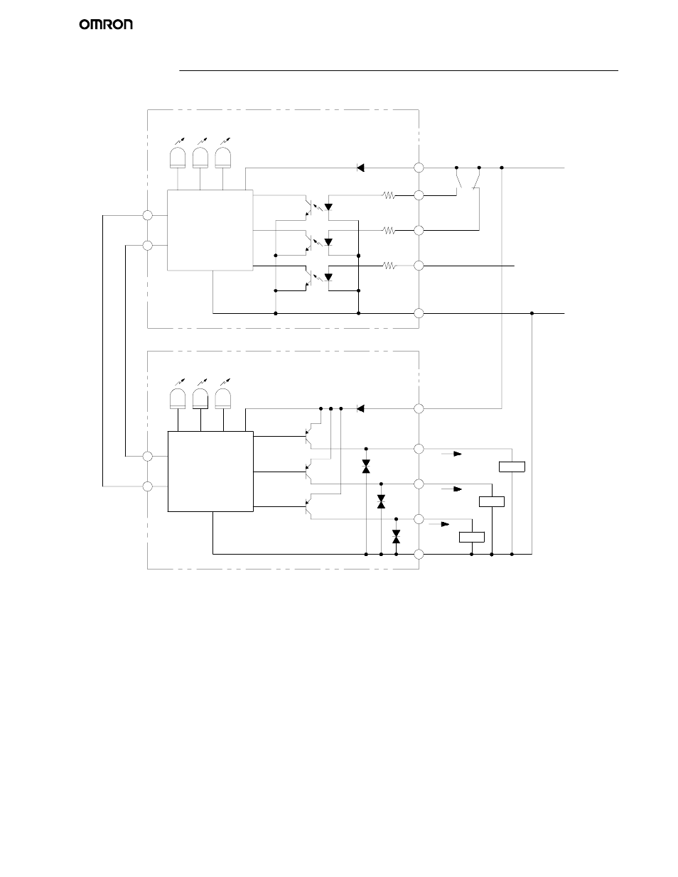
I/O CIRCUIT DIAGRAM
IR--light
indicator
2
3
1
4
7
ON--state
indicator
2
7
Instability
indicator
3
1
4
5
6
6
5
Green
Brown
White
Yellow
Blue
Brown
Green
White
Yellow
Pink
Grey
Pink
Grey
+24 V
0 V
Load
Load
Load
Instability
Blue
output
R
S
--485(
A
)
R
S
--485(
B
)
Interlock
indicator
Ext. test/blanking
indicator
External test
input
Interlock selection
input
Relay monitoring
input
Main emitter
circuit
Main receiver
circuit
Control output 1
Control output 2
OFF--state
indicator