F3s-b, Jconnector (main unit end) – Omron F3S-B User Manual
Page 12
F3S-B
13
J
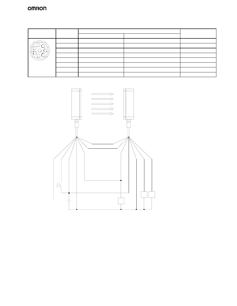
CONNECTOR (MAIN UNIT END)
Front view
Pin no.
Signal name
Wire color
Receiver
Emitter
of Extension Cable
1
Control output 2
Relay monitoring input
White
1
7 6
2
24 VDC
24 VDC
Brown
1
2
8
6
5
3
Control output 1
External test input
Green
2
8
5
3 4
4
Instability output
Interlock selection input
Yellow
3 4
5
RS-485 (A)
RS-485 (A)
Grey
6
RS-485 (B)
RS-485 (B)
Pink
7
0 V
0 V
Blue
8
N.C. / reserved
N.C. / reserved
Red
Note: N.C. / reserved: do not connect
RS--485(A) (Grey 5)
RS--485(B) (Pink 6)
Receiver
Emitter
K2
K1
K3
E1
S1
E1:
24 VDC Power supply
S1:
External test switch
K1, K2: Relay or PLC input to control the dangerous
movement of a machine
K3:
Relay to indicate unstable condition
24
VDC
(Bro
w
n
2)
Ex
t.
tes
t(G
reen
3)
R
elay
m
onitor
ing
(W
hite
1)
0V
(B
lu
e7
)
O
utput
1
(G
reen
3)
Instability
(Y
ellow
4)
Inter
lock
selection
(Y
ellow
4)
24
VDC
(Bro
w
n
2)
0V
(B
lu
e7
)
O
ut
pu
t2(
W
hi
te1
)