F3s-b, Jdetails of f39-eu1e optional function kit, Caution – Omron F3S-B User Manual
Page 13: Preparation
F3S-B
14
RS--485(A) (Grey 5)
RS--485(B) (Pink 6)
K3
E1
S1
k1
k2
E1
S2: Restart interlock reset switch
S2
Emitter
Emitter
Receiver
k1, k2: Auxiliary contact to moni-
tor the condition of the final relay
24
VDC
(Bro
w
n
2)
0V
(B
lu
e7
)
Instability
(Y
ellow
4)
Inter
lock
selection
(Y
ellow
4)
24
VDC
(Bro
w
n
2)
0V
(B
lu
e7
)
R
elay
m
onitor
ing
(White
1)
Ex
t.
tes
t(G
reen
3)
24
VDC
(Bro
w
n
2)
0V
(B
lu
e7
)
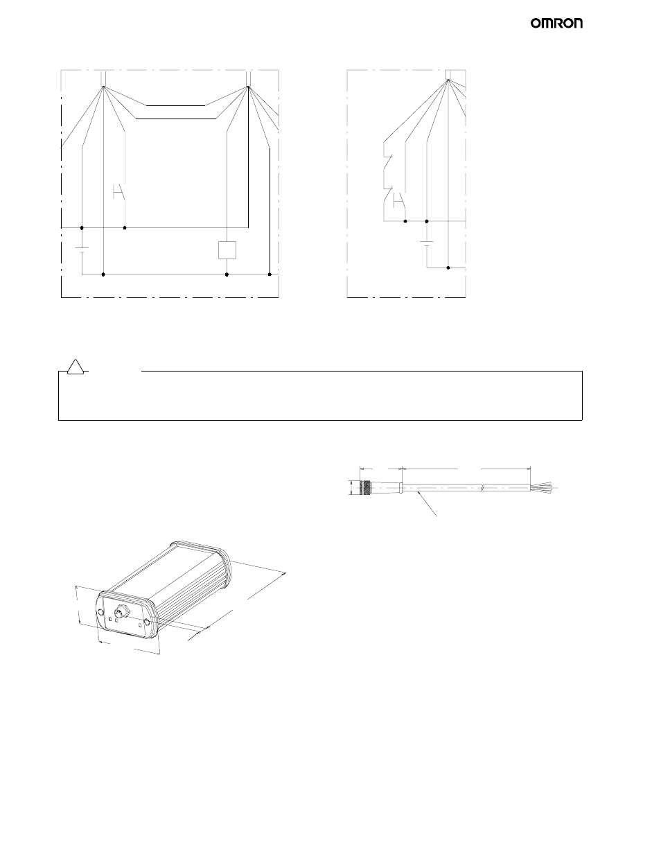
When Using START/RESTART FUNCTION
When Using Optional RELAY MONITORING FUNCTION
J
DETAILS OF F39-EU1E OPTIONAL FUNCTION KIT
Preparation
Caution
Perform the installation check and the periodical inspection described in the F3S-B manual.
Do not disassemble, repair or modify the F39-E1.
Do not use the F39-E1 in flammable or explosive environments.
!
To use the F39-U1E software, the following items are necessary.
•
Personal Computer (not included)
-- Windows 95, Windows 98, or Windows NT
-- 133MHz Pentium processor or better
-- 32MB RAM or higher for Windows 95 and Windows 98
-- 64MB RAM or higher for Windows NT
-- A 115kBd RS-232 serial interface port or better
•
F39-E1 Interface Unit
114
8
35
60
•
F39-JB1C Interface Cable 5 m cable length,
M8 connector (4 pins)
30.5
5000
Round vinyl--insulated cord
5 mm dia. (32/0.1 mm dia.) 4 cores
∅ 15
•
RS-232C Cable (not included)