Specifications, F3s-b, Jstand-alone type – Omron F3S-B User Manual
Page 3: Jseries connection types, Jrating and performance
F3S-B
4
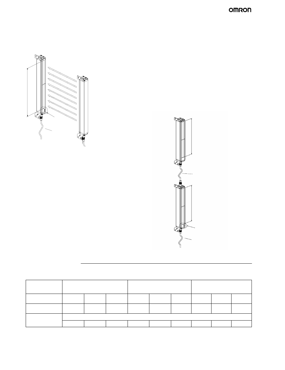
Receiver
Emitter
Indicator area
Extension cable
P
rotective
height
J
STAND-ALONE TYPE
This is the most common configuration, and it is used to
protect a hazardous part of a machine when approached
from one direction only.
J
SERIES CONNECTION TYPES
When your application requires an additional protective zone,
for example, to prevent someone from staying behind a primary
detection zone, the F3S-B may be connected in series. The
system consists of a Master Unit, a Slave Unit, and a series
connection cable, type F39-JB1B.
The series connection allows up to 96 axes and 2.4 m of
protective height in total.
Series connection types have the same characteristics as
stand-alone types. When the detection zone of the Master Unit
or that of the Slave Unit is interrupted, the outputs of the Master
Unit go to the OFF-state.
Note: Slave Unit does not have indicators.
Master Unit and Slave Unit need to be ordered
separately.
Protective height
Series connection cable
Slave Unit
Indicator area
Extension cable
Master Unit
Protective height
Specifications
J
RATING AND PERFORMANCE
Type
F3S-BjjjP (See Note 1.)
Stand-Alone
F3S-BMjjjPjj (See Note 1.)
Master Unit for series connection
F3S-Bjjj (See Note 1.)
Master Unit for series connection
No. of optical axes
(Beams)
12 to 66
6 to 33
4 to 22
12 to 66
6 to 33
4 to 22
12 to 30
6 to 15
4 to 10
Optical-axis pitch
(Beam pitch)
25 mm
50 mm
75 mm
25 mm
50 mm
75 mm
25 mm
50 mm
75 mm
Optical resolution
(Detection
Non-transparent: in diameter
(Detection
capability)
30 mm
55 mm
80 mm
30 mm
55 mm
80 mm
30 mm
55 mm
80 mm
(This table continues on the next page.)
Note:
1
For detailed type names and optical specifications, see Ordering Information.