Installation – Outback Power Systems GS8048 User Manual
Page 38
Installation
36
900-0021-01-00 Rev A
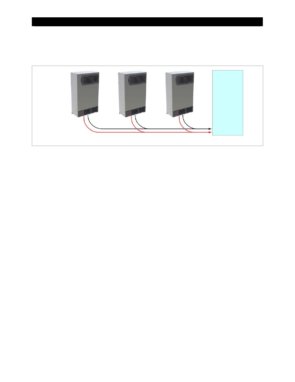
In parallel stacking, two or more inverters are stacked to create a single, common 120/240 Vac bus.
All inverters share a common L1 and L2 input (AC source) and run loads on a common L1 and L2 output.
Up to ten inverters may be installed in a parallel arrangement. The example on this page shows three
inverters. The wiring diagram on the next page shows two.
Figure 26 Example of Parallel Stacking Arrangement (Three Inverters)
When installing a parallel system, the following rules must be observed.
Parallel stacking requires the MATE3 system display and a HUB.
One inverter,and one inverter only, is always the master and is programmed as Master. This is the default
setting. (See the MATE3 manual for programming.)
The master must be connected to port 1 of the HUB. Other inverters must not be selected as master.
All slave inverters, regardless of quantity, should be selected as Slave during programming.
All overcurrent devices must be sized for 50 Aac or less.
All wiring must be sized for 50 Aac or more.
All output circuit breakers must be sized appropriately for loads and inverter wattage.
The AC input (generator or utility grid) must be 120/240 Vac at 60 Hz (split-phase).
When wiring the AC source to the inverters, local codes may require the inverter circuits to be located at the
opposite end of the panel from the main circuit breaker. This prevents overloading of the AC bus.
24 kVA
120/240 Vac
8 kVA
120/240 Vac
8 kVA
120/240 Vac
8 kVA
120/240 Vac