Ac wiring, Installation – Outback Power Systems GS8048 User Manual
Page 28
Installation
26
900-0021-01-00 Rev A
AC Wiring
WARNING: Shock Hazard
Ensure there is only one AC neutral-ground bond at any time. Some codes
require the bond to be made at the main panel only. The GSLC is equipped with
its own bond, which may need to be removed.
IMPORTANT:
The AC input and output must be protected with branch-rated circuit breakers
of up to 50 Aac maximum size to meet NEC or other code requirements.
The Radian inverter/charger’s AC terminal block has nine positions for AC wires. The minimum
recommended wire size is #8 AWG (0.013 in
2
) or 10 mm
2
. Larger wire gauges may be required for
specific conditions. The largest size that can be used with the terminals is #6 AWG (0.021 in
2
) or
16 mm
2
.
The inverter makes its AC connections using spring-loaded clamps. It is necessary to strip
approximately ½ inch (1 cm) of insulation from the end of each wire. Other tools are not required.
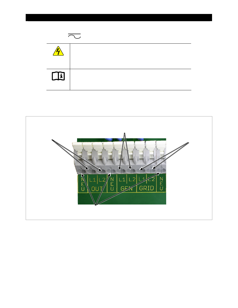
Figure 15 AC Terminals
The terminals labeled L1 and L2 Grid are used to connect to the two utility grid “hot” wires. The L1
and L2 wires are usually black and red respectively, and read 120 Vac each when measured with
respect to neutral. In a standard service, L1 and L2 are 180 degrees out of phase, and should read 240
Vac when measured from one to the other.
The L1 and L2 Gen terminals are used to connect to the “hot” wires on a 120/240 Vac generator.
All system wiring must comply with national and local codes and regulations.
NOTE: The terminals are labeled for grid and generator due to common conventions, not because of
inverter requirements. Each input can accept any AC source as long as it meets the requirements of
the Radian inverter and the selected input mode. (See the Operator’s Manual). If necessary, the Gen
terminals can accept grid power. The opposite is also true.
L1 and L2 Out
Neutrals
L1 and L2
Grid
L1 and L2 Generator