Appendix b: periodic error correction (pec) – Orion ATLAS EQ-G User Manual
Page 23
23
view (Figure 19). This will determine which direction (left
or right) moves Polaris closer to the center of the eyepiece
field of view.
12.Carefully and gently loosen both the tube ring attachment
screws (Figure 3) by a couple of turns.
13.Make adjustments to the optical axis offset adjustment
screws (the socket head cap screws located at each
corner of the mounting plate, (Figure 3) according to the
results of step 11. If Polaris moves toward the center when
the telescope is pushed as indicated in Figure 19, loos-
en the adjustment screws near the front of the tube and
tighten the adjustment screws closer to the back of the
tube (Figure 20a). If Polaris moves away from the center
when the telescope is pushed as in Figure 19, loosen the
adjustment screws near the back of the tube and tight-
en the adjustment screws closer to the front of the tube
(Figure 20b). Look into the eyepiece. Adjust the adjust-
ment screws just enough to place Polaris HALF the dis-
tance back to the center of the illuminated reticle eyepiece
(Figure 21).
14.Repeat steps 7 to 12 until Polaris remains in the center
of the eyepiece field of view, or moves slightly around the
center, when the mount is rotated about the R.A. axis.
Note: This calibration method can be applied to both refract-
ing and reflecting telescope designs. Differences in the optical
path of telescopes do not affect how the telescope tube and
tube rings should be adjusted on the mounting plate.
appendix B: Periodic Error
correction (PEc)
Using the PEC functions requires an illuminated reticle eye-
piece capable of producing at least 300X magnification when
used with your telescope. For best results, the true field of
view should not exceed 10 arcminutes.
Periodic errors are inherent in almost all worm gears due to
slight eccentricities and misalignments. The PEC (Periodic
Error Correction) Training function provides a manual correct-
ing method to reduce the amplitude of the worm gear errors.
By recording a full cycle of guiding actions, the Atlas EQ-
G can compensate for drifting in the R.A. sidereal tracking
caused by periodic errors. The following instruction will lead
you on a step-by-step procedure for performing the PEC.
Note: The PEC training function is recommended for advanced
users with interest in long-exposure astrophotography only.
Careful guiding is required. Standard sidereal tracking is suf-
ficient for all casual visual applications of the Atlas EQ-G, and
PEC training is not required
.
PEc training
1. Perform an accurate polar alignment using the polar axis
finder scope.
2. Manually point or electronically slew the telescope mount-
ed on the Atlas EQ-G to a star with a small value Dec.
coordinate (Dec. between +10° and –10°). This object will
be used as the guide star.
3. Activate “Sidereal Tracking” from the Setup menu (see
“Setup Functions”). Once tracking has initiated, press
ESC
to return to the Setup menu.
4. Rotate the reticle eyepiece in the focuser (or diagonal)
until the R.A. movement of the star becomes parallel to
one of the illuminated crosshairs
5. Move the guide star designated in step 2 to the center of
the eyepiece field of view using the direction buttons.
6. On the hand controller, select “PEC Training” in the Utility
Functions and press
ENTER.
Note: Utility Functions can be accessed by pressing the
UTILITY quick rererence button on the hand controller.
7. Select the R.A. guide speed for the PEC Training. You have
two guide speed choices: 1) 0.25X and 2) 0.5X. Press the
numeric button 1 to choose a guide speed of 1.25X or
press 2 to choose a guide speed of 1.5X.
8. The Atlas EQ-G hand controller will display the current
time once the guide speed has been selected, indicating
the recording has begun.
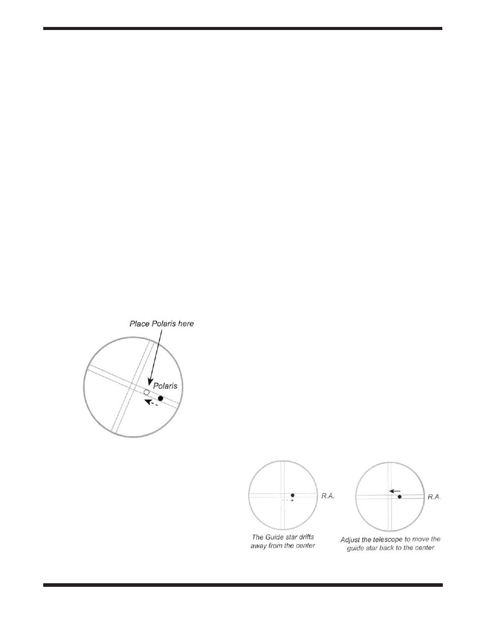
9. Using the left or right direction button only, move the tele-
scope so the guide star remains centered in the eyepiece
field of view (Figure 21). Repeat as necessary.
The Atlas EQ-G hand controller will record the manual guid-
ing actions for 8 minutes in order to characterize the periodic
Figure 21.
Using the optical axis offset screws move Polaris
halfway to the eyepiece’s center.
Figure 22.
Drifting caused by periodic error.