Installation, Mounting, Rack mounting – RuggedCom RSG2300 User Manual
Page 12
3. Installation
RuggedCom® RuggedSwitch®
12
RSG2300 Installation Guide Rev 110
3. Installation
3.1. Mounting
RSG2000 series products are designed for maximum mounting and display flexibility. Customers
can order an RSG2000 series switch that can be mounted in a standard 19" rack, 1" DIN Rail,
or directly onto a panel.
3.1.1. Rack Mounting
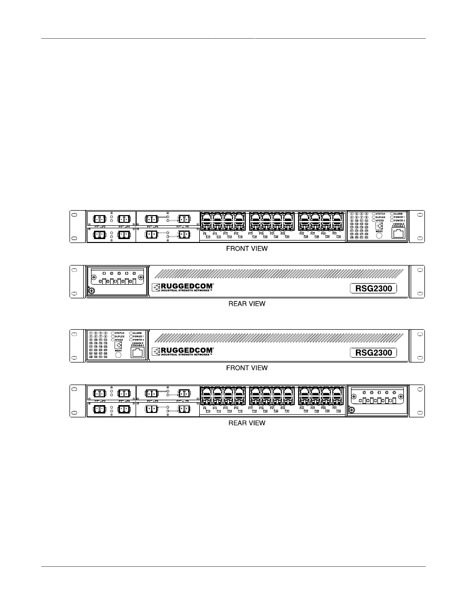
For rack mount installations, the RSG2000 series can be ordered with connectors on the front
panel or on the rear of the chassis. Placing the connectors on the rear allows all data and power
cabling to be installed and connected at the rear of the rack. See the front and rear rack mount
chassis orientation options below for examples of rack mount orientation.
Figure 3.1. RSG2300 Rack Mount Chassis Orientation: Front Mount
Figure 3.2. RSG2300 Rack Mount Chassis Orientation: Rear Mount
The RSG2000 family of products can be rack mounted using the included rack mount adapters.
Secure the rack mount adapter to the front side of the chassis using the included black PAN head
Phillips screws in the positions shown in
Figure 3.3, “Rack Mount Adapter Mounting Locations”
.
The entire chassis can then be mounted to a standard 19" rack. Two additional rack mount
adapters are included to optionally secure the rear of the chassis in high-vibration or seismically
active locations.