RAD Data comm ASMi-31 User Manual
Page 60
Appendix D. DTE Interface Connectors
ASMi-31 Installation and Operation Manual
D-4
General
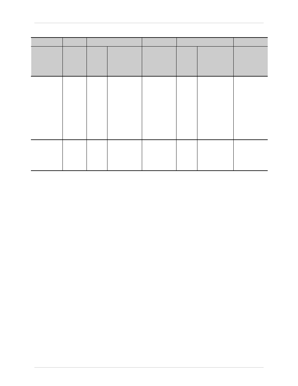
Table D-1 DTE Interface Signal Assignments (Cont.)
RS-232
V.35
EIA-530
X.21
Signal
Function
DB-25
Stand-
alone
and
Frame
DB-25
Frame
34-pin
Standalone
Pin Circuit
DB-25
Standalone
and Frame
Pin Circuit
DB-25
Frame
DB-15
Standalone
Pin Circuit/
(Function)
Description
Remote
Loopback
21
21
N and h
140
21
RL
A control signal
input; when
on, commands
ASMi-31 to
send a remote
Loopback
command
(V.54 Loop 2)
to the remote
ASMi-31. See
Table 2-1.
Test Indicator
25
25
n and k
142
25
TM
A control signal
output from
ASMi-31;
positive during
any test mode.
Order from: Cutter Networks
Ph:727-398-5252/Fax:727-397-9610
www.bestdatasource.com