Installation and operation, A.5 installation and operation, Figure a-5 ethernet bridge layout (utp option) – RAD Data comm ASMi-31 User Manual
Page 46: Figure a-6 ethernet bridge layout (bnc option)
Appendix A. Ethernet Interface
ASMi-31
Installation and Operation Manual
A-4
Installation and Operation
A.5 Installation and Operation
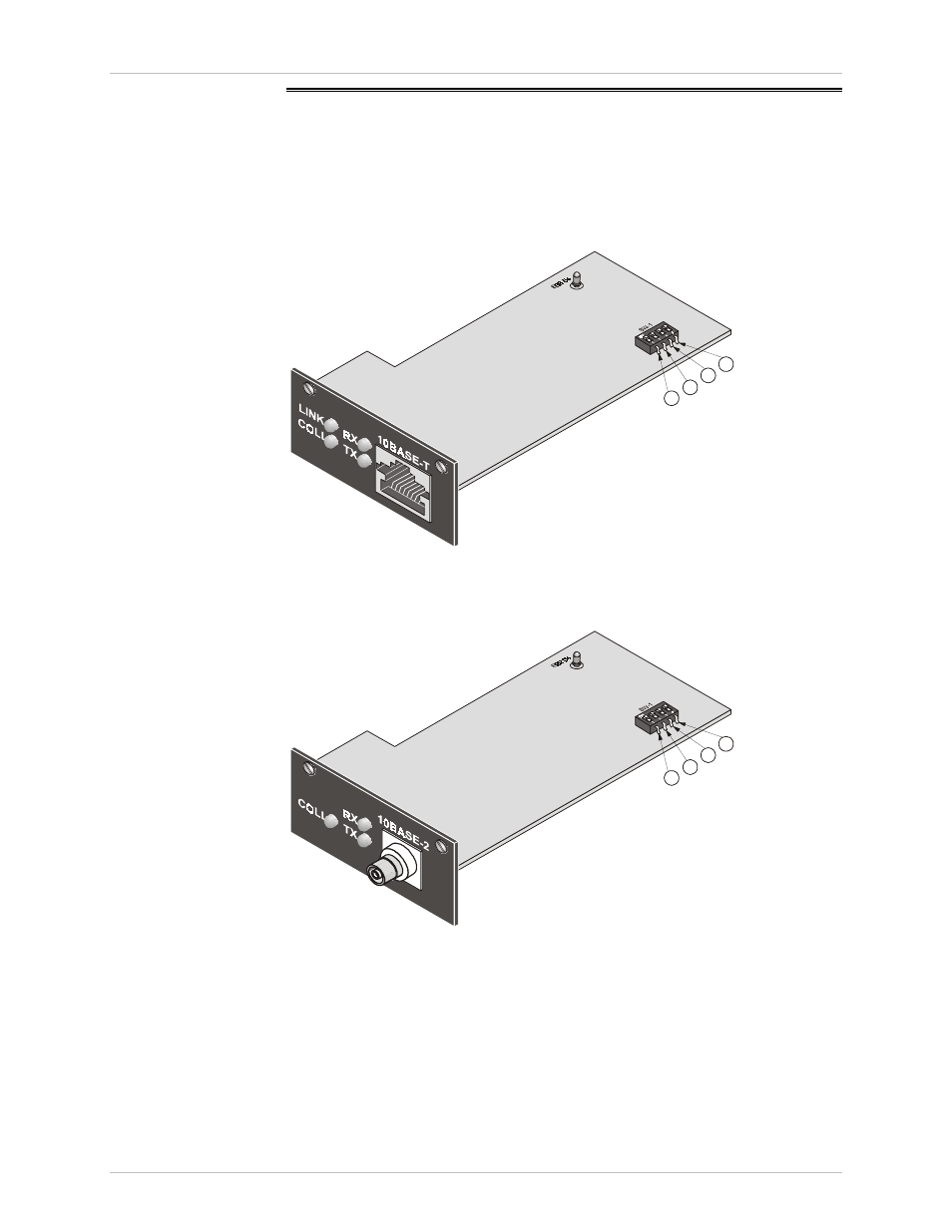
Figure A-5 and Figure A-6 show the Ethernet bridge layout, the locations of
the DIP switches, and the rear panel components for the UTP and the BNC
versions, respectively.
1
2
3
4
Figure A-5 Ethernet Bridge Layout (UTP Option)
1
2
3
4
Figure A-6 Ethernet Bridge Layout (BNC Option)
Order from: Cutter Networks
Ph:727-398-5252/Fax:727-397-9610
www.bestdatasource.com