Ext mode, C.3 ext mode – RAD Data comm ASMi-31 User Manual
Page 55
ASMi-31 Installation and Operation Manual
Appendix C. X.21 Interface Module
EXT Mode
C-3
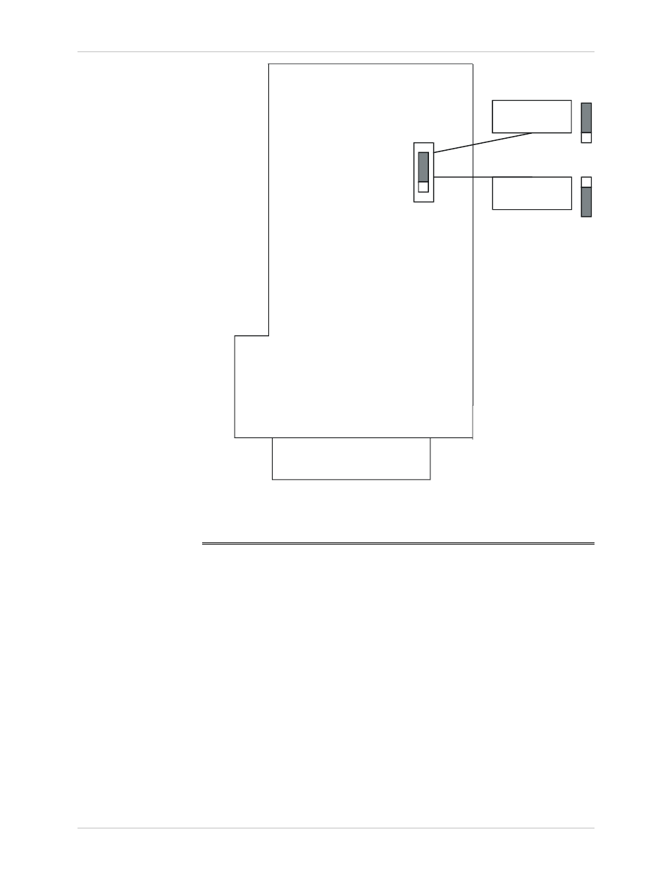
JP 2
INT/RCV
clock setting
EXT
clock setting
Connector DB-15
EX
T
Figure C-3 Location of Jumper JP2 in the IR-X.21 Interface Module
C.3 EXT Mode
This mode is used in applications of X.21 networks where the system timing
is provided by the X.21 network. The IR-X.21 module has an internal buffer
to compensate for the phase delay introduced to the system by the line
delay between the two modems. The buffer is a 16-bit FIFO connected as
shown in Figure C-4. When the modem's clock mode is EXT, the JP2 jumper
must be set to EXT (see Figure C-3).
Order from: Cutter Networks
Ph:727-398-5252/Fax:727-397-9610
www.bestdatasource.com