RAD Data comm ASMi-31 User Manual
Page 27
ASMi-31 Installation and Operation Manual
Chapter 2. Installation and Setup
16-05-01 13:37
Installation and Setup
2-7
➤
➤
➤
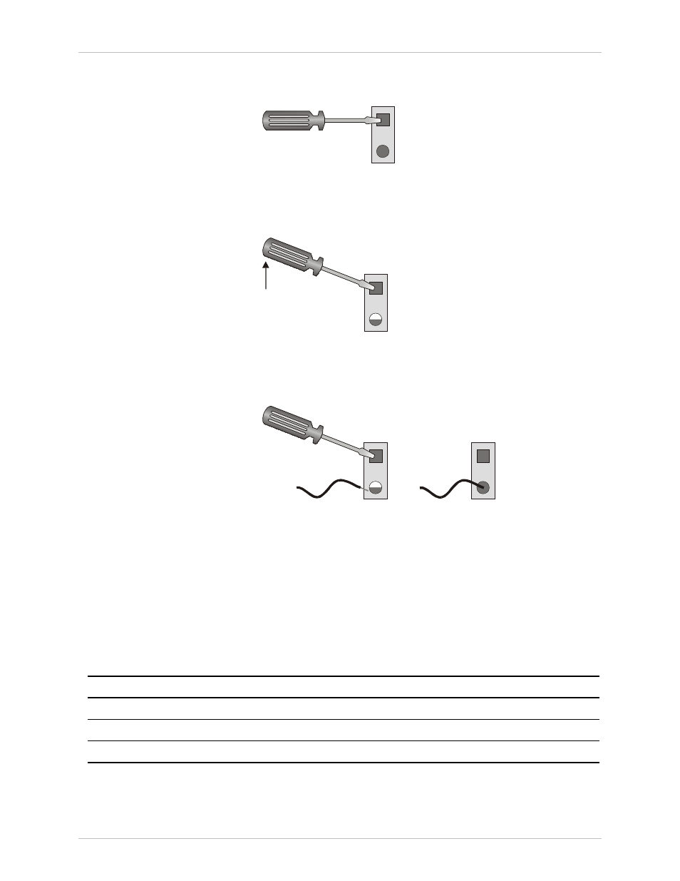
➤ To connect the line:
1. Insert the screwdriver into a square hole (see Figure 2-3).
Figure 2-3 Connecting the Line – Step 1
2. Raise the inserted screwdriver, putting pressure on the ramp within the
square hole (see Figure 2-4).
Figure 2-4 Connecting the Line – Step 2
3. Insert the stripped end of the wire and remove the screwdriver (see
Figure 2-5).
Figure 2-5 Connecting the Line – Step 3
Connecting the DTE
The rear-panel DTE connector provides interface for data input/output,
clock reference and control signal exchange between ASMi-31 and the DTE.
The DTE interface is changeable module with the interface connector. The
DTE is connected to ASMi-31 via adapter cables depending on the interface
type, see Table 2-2 to select the correct cable for your DTE interface.
Table 2-2 DTE Interfaces and Matching Adapter Cables
DTE Interface
Connector Description
RAD Cable
V.24/RS-232
25-pin, D-type, female
CBL-HBT/V24
V.35
34-pin, female
CBL-HBT/V35
X.21
15-pin, female
CBL-HBT/X21
Order from: Cutter Networks
Ph:727-398-5252/Fax:727-397-9610
www.bestdatasource.com