Installation and operation, A.3 installation and operation – RAD Data comm ASM-60 User Manual
Page 39
ASM-60 Installation and Operation Manual
Appendix A IR-ETH Interface Module
Installation and Operation
A-3
A.3 Installation and Operation
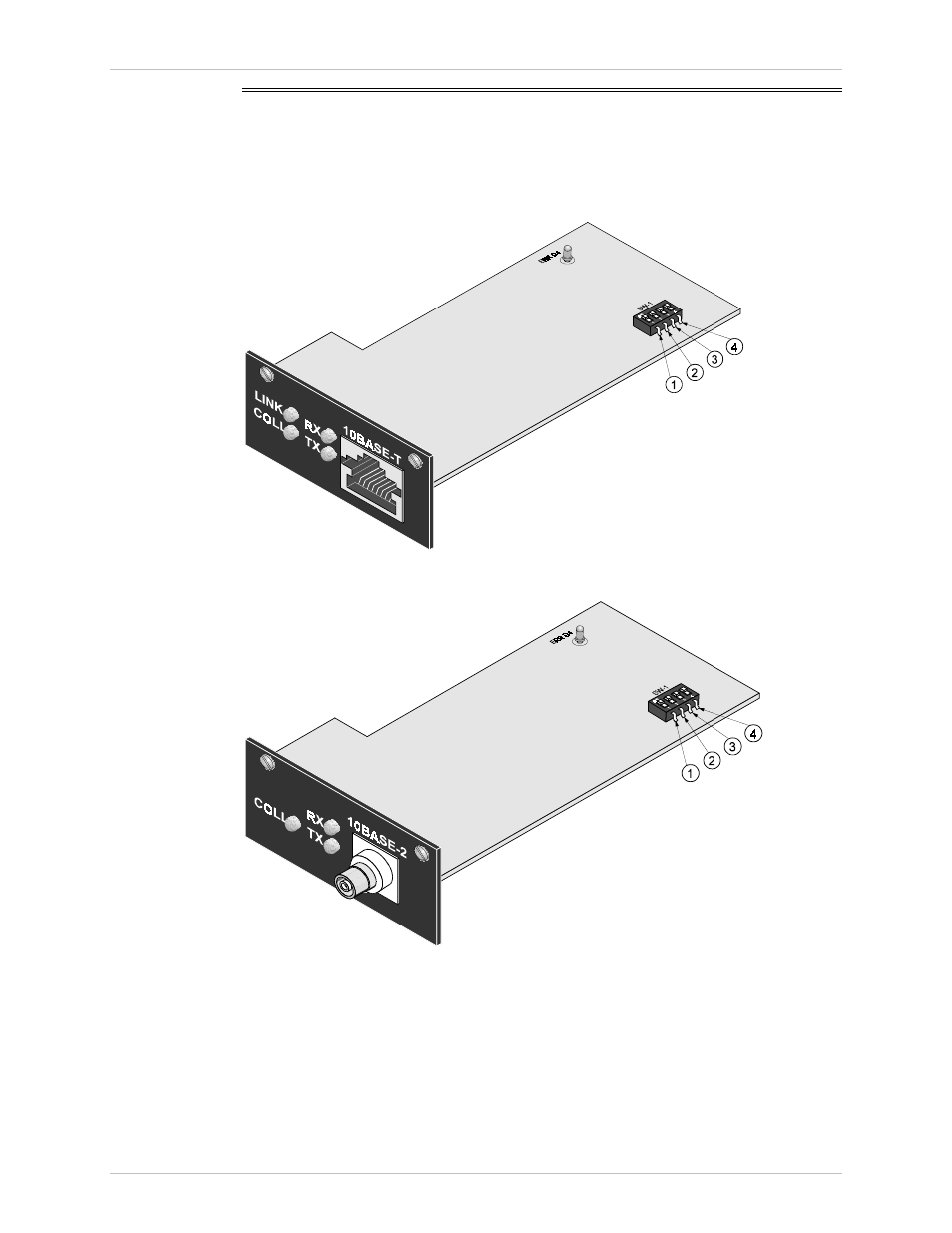
Figure A-4 and Figure A-5 show the Ethernet bridge layout, the locations of the DIP
switches, and the rear panel components for the UTP and the BNC versions,
respectively.
Figure A-4. IR-ETH Layout (UTP Option)
Figure A-5. IR-ETH Layout (BNC Option)