Operating asm-60, Turning on asm-60, Normal indications – RAD Data comm ASM-60 User Manual
Page 22: Turning off asm-60, 2 operating asm-60
Chapter 3 Operation
ASM-60 Installation and Operation Manual
3-2 Operating
ASM-60
Table 3-1. ASM-60 LED Indicators (Cont.)
Name Function
SYNC A (red/green)
ON (red) – Data link A is not synchronized with the remote modem.
ON (green) – Data link A is synchronized with the remote modem.
SYNC B (red/green)
ON (red) – Data link B is not synchronized with the remote modem.
ON (green) – Data link B is synchronized with the remote modem.
3.2 Operating ASM-60
Turning On ASM-60
ASM-60 is turned on as soon as the power is connected to the unit. The PWR
indicator lights up and remains lit as long as ASM-60 receives power.
ASM-60 requires no operator attention once installed, with the exception of
occasional monitoring of front panel indicators. Intervention is only required for
the ASM-60 configuration events monitoring.
Normal Indications
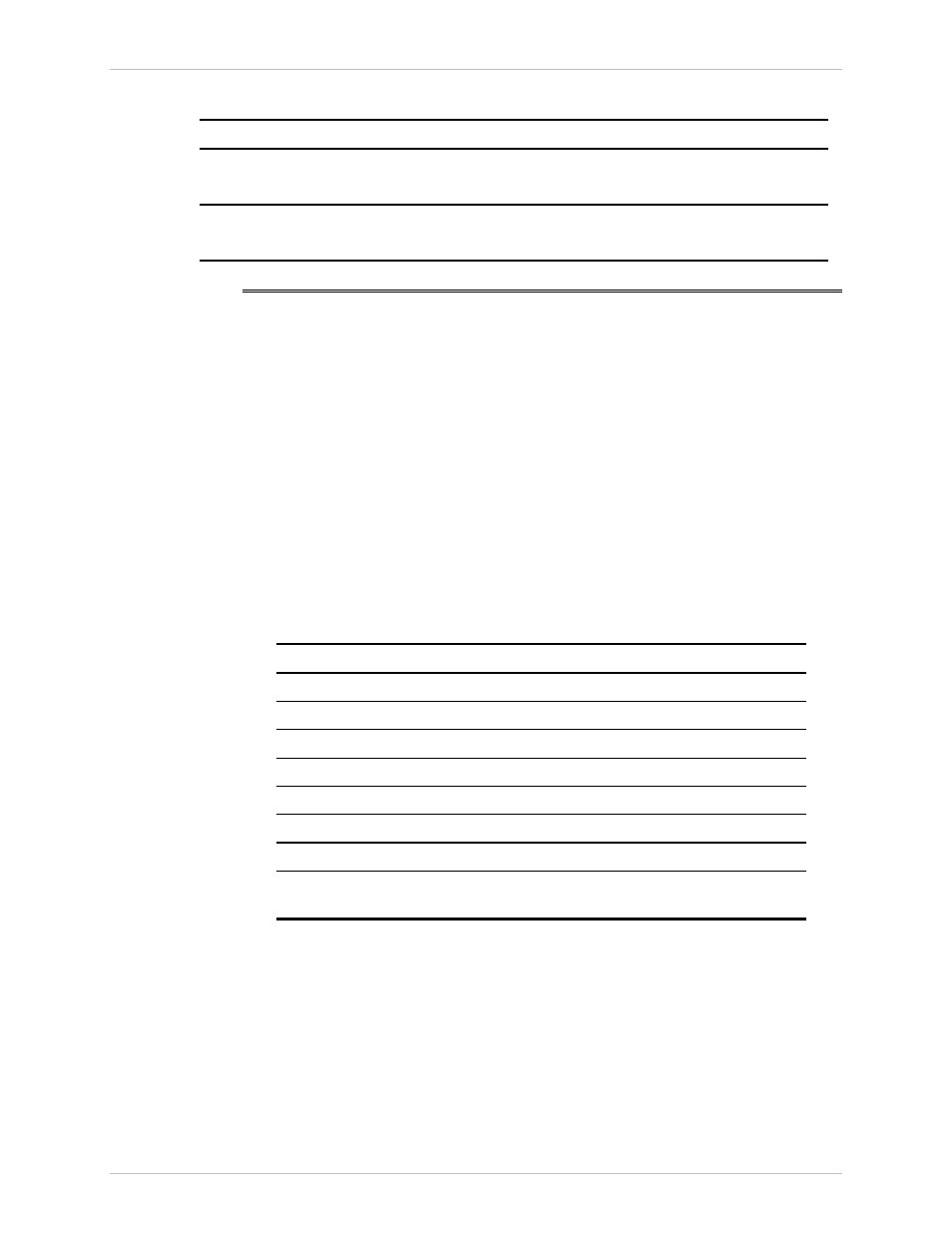
Table 3-2 shows the status of the ASM-60 indicators, a few seconds after
power-up.
Table 3-2. ASM-60 Indicator Status
Indicator Status
PWR ON
TD
Depends on DTE data transmission.
RD
Depends on DTE data transmission.
RTS
Depends on DTE RTS signal status.
DCD
Depends on remote modem data transmission.
TST OFF
ALM OFF
SYNC A/SYNC B Green or red, depending on remote modem data
transmission.
If the above LED indications are not obtained following initial power turn-on, refer
to Chapter 5 for the diagnostic test instructions.
Turning Off ASM-60
To turn off ASM-60, remove the power cord from the power source.