Chapter 3. operation, Front panel indicators, Chapter 3 operation – RAD Data comm ASM-60 User Manual
Page 21: 1 front panel indicators
Front Panel Indicators
3-1
Chapter 3
Operation
This chapter provides the description of the ASM-60 front-panel indicators, and
details the modem's operating procedures (turn-on, front-panel indications,
performance monitoring and turn-off).
Installation procedures given in Chapter 2 must be completed and checked before
attempting to operate ASM-60.
3.1 Front Panel Indicators
The front panel of ASM-60 includes nine LED indicators that show the current
operating status of the unit.
ASM-60 also includes a proprietary 9-pin connector (CONTROL DCE) on its front
panel for connection to a terminal.
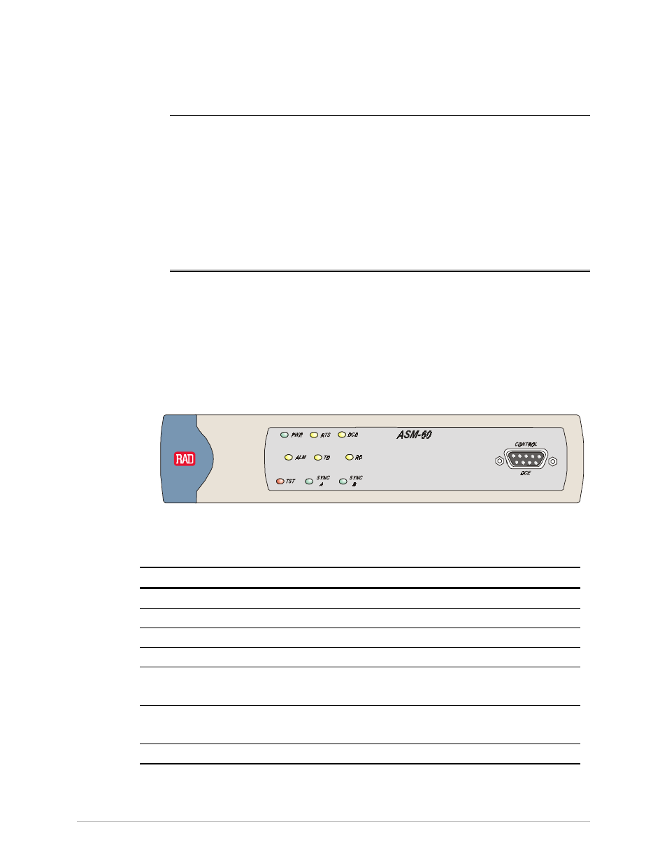
Figure 3-1 shows the ASM-60 front panel. Table 3-1 lists and describes the ASM-60
indicators.
Figure 3-1 ASM-60 Front Panel
Table 3-1. ASM-60 LED Indicators
Name Function
PWR (green)
ON – Power is ON.
RTS (yellow)
ON – DTE activates Request To Send.
DCD (yellow)
ON– Link A, link B and internal IMUX are synchronized.
ALM (red)
ON – An alarm enters the alarm buffer.
TD (yellow)
ON – Data is being transmitted to the DTE.
OFF – Steady mark is being transmitted.
RD (yellow)
ON – Data is being received from the DTE.
OFF – Steady mark is being received.
TST (red)
Reserved for future use